Monday, August 7, 2017

Velomobile Ridekick Power Trailer Fender Progress!

The last couple of days have been the best that it could be while working on the new fenders for the velomobile Ridekick power trailer project. This little trailer will supply power to the velomobile to make climbing hills easier.  It has a range of 35-40 miles at 20 mph so it should do the job nicely.  I wanted to get this post out to everyone to get you caught up on the progress that I've made on the project over this past week.


Here are a couple images that I created of the design I am talking about that I posted a little while ago just to remind everyone where I am heading with it.  So let's get started on how I put the fenders together.


This was the first step.  I cut three pieces of one inch Styrofoam which were 15 1/2 inches square.  The foam in standard building construction foam that you can buy at your local builders store.  I glued the foam together using Foam Fusion adhesive from the Hotwire Foam Factory.  This glue looks like regular white glue you would use for wood but can still be cut using a hotwire tool and is made specifically for foam.  Great stuff.  I let this sit over night to dry properly.


I then marked out a 14 1/2 diameter circle on the foam and cut it out using my band saw. This worked out perfectly as you can see. The new disk gave me enough material to make both fenders for the power trailer.
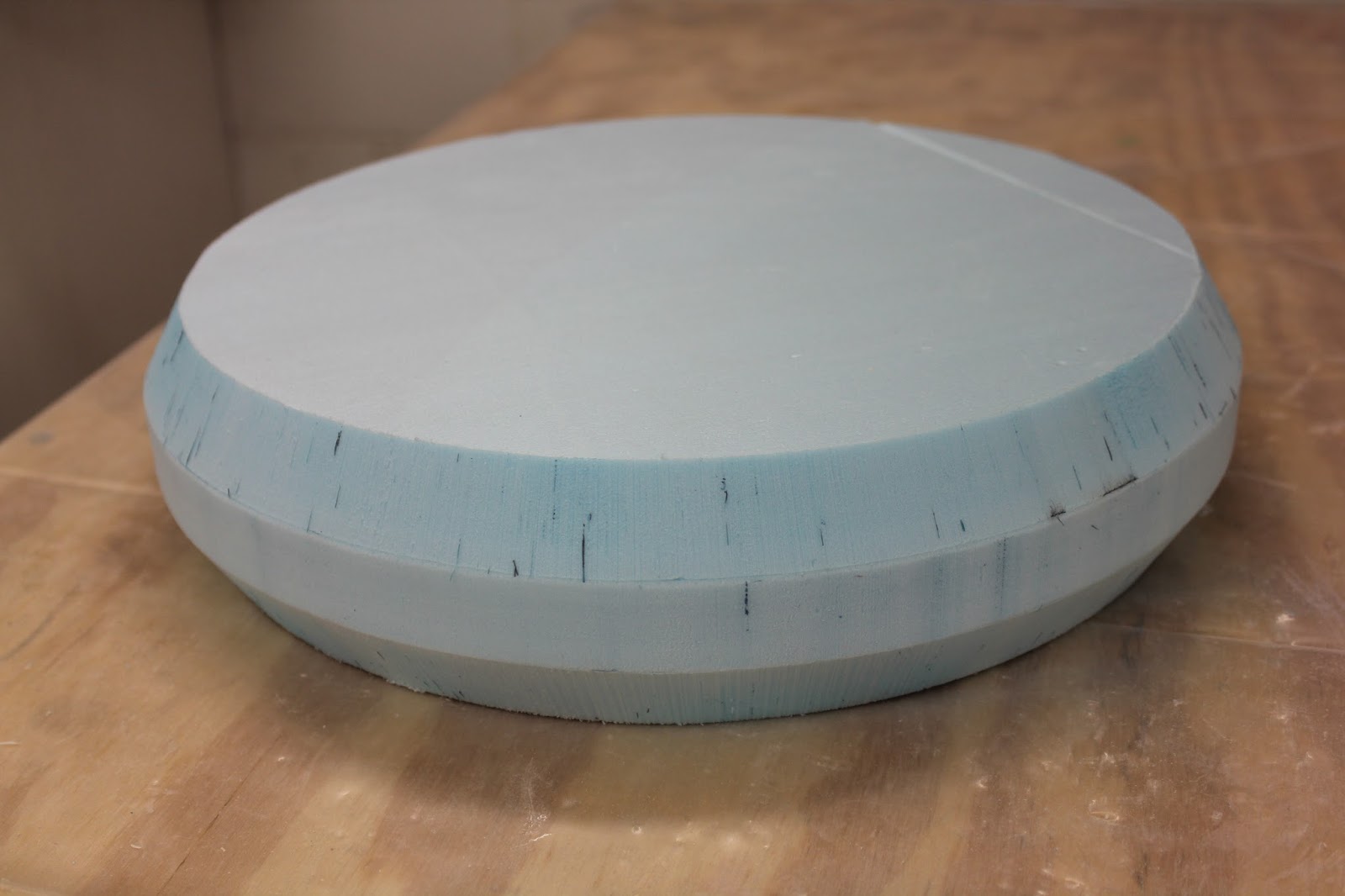

Now the next step took me a bit more time to figure out.  I needed to cut down the amount of material I needed to get the correct shape for the fenders.  Rather than do a ton of sanding I tipped the table on the band saw 30 degrees and then ran the foam disk up against the rip fence.  I had used a temporary guide so I knew how deep the cuts should be so I could retain the shape I was going for.  Again my planning paid off nicely.


The next test was similar to the first except I needed to change the set up a bit on the band saw.  On the first cut the disk was laying flat like you see in the photo above.  To make the second cuts I needed to place the disk on the band saw so it was sitting like I was going to roll the disk on the table.  This made the second cuts as I had planned  a bit more difficult to do but after I was done  I could stop holding my breath when I completed this step in the process.


Next I started sanding the foam into shape to make the mold for the fenders.  Sanding the foam is very easy so I just took my time and worked my way around one side sanding at an angle to the edges that I had cut.  As you can see the part was starting to shape up nicely now.


Here the foam disk has been completely sanded smooth into the shape that I wanted for the fenders.  The marks on the foam piece are guides that helped in cutting the disk apart later on in the process.


In the fender design I needed to make a small protrusion that would mount the fenders to the lid of the trailer.  This protrusion allows for correct alignment of the mounting hardware and clearance for the tire when the fenders are in place.  I cut two small 1 1/2 inch thick foam blocks to be used to make the protrusions for the fenders.  The only reason the foam is not blue like the disk is that I had some two inch pink foam laying around in the shop that was perfect for the job.

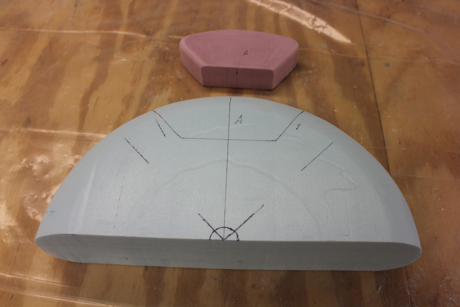

Here you can see the foam disk has now been cut in half and this will be the start of one of the fenders.  I have marked out where the pink foam block should be located on the half disk so the next step was to remove the foam that was not needed to install the new foam block.


I laid the foam half disk on the table and used a hot wire rod tool and a 2 x 4 to cut out the foam that I needed to remove.  This only took a couple of minutes and made a nice clean job of the task in the process. 


After both half disk parts had been modified to accept the pink foam blocks it was just a matter of inserting them into the new cavities that I had created and bonding them into place using fiber glass epoxy resin and micro-balloons to putty them into place.


In the photo above you can see that the pink block has been mounted in place and a couple layers of fiberglass have been applied to the outer surface of the foam.  The white half circle of card stock was used to mark out where I needed to cut the foam to create the fender shape I was going for. 


After the first couple of layers of glass had been placed on the foam I realized that there was nowhere near enough glass on the parts to make the fenders strong enough or stiff enough to make them useable.  So I went to work adding the additional layers that were needed.  In all I started with two layers of 3 oz. glass, then four layers of 8 oz. glass and then two more layers of 3 oz. glass to finish the parts off. 


After adding the additional glass and letting the parts cure over night I again marked where I needed to cut to make the fenders using my cardstock template.  This was much easier to see where I needed to cut once again.


With the Styrofoam shape being flat enough to lay on the band saw table top I was able to make the first cut going all the way through the part to remove the inner section of the foam form.  I took my time and was able to get a useable cut that was very close to near perfect.  I will have to tweak it a bit but it should not be a difficult task as long as I take my time with it.
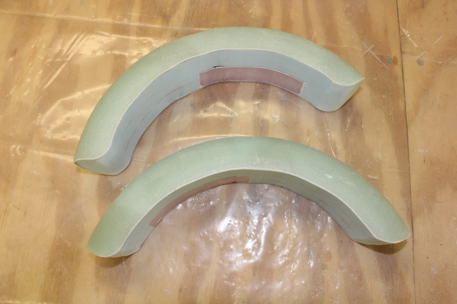

Here both fenders have been cut and the corners of the foam have been rounded off nicely to get the shape I was shooting for.  They look like fenders already.  Again I was very pleased with the results and progress I had made in only a couple of days.


The next step was to remove all of the foam that was on the inside of the fenders.  Again I used a hotwire tool for this part of the project.  This tool looks like a wire loop with a handle on it that heats up to easily melt the foam and cut out what is not needed.  The entire process only took about ten minutes to get to this point. After that I took a small pocket knife and scraped away any foam left over from the first pass and then finally sanded the inner surface with sand paper to clean up what remained. 


Once I had the fender completely cleaned I temporarily placed them on to the trailer just to see what they looked like.  I used small blocks of Styrofoam to hold the fender on to the top of the tire and took the photos that you see here.  I am very pleased with the look of the fenders and how they turned out.  In the photos the fenders actually are a little high but this will be corrected one I get the mounts dialed in to get the fenders lowered just a little bit.  This again will take a little time but I am in no rush at this point to hurry only to mess things up now.  
  I will work on the mounts in the next couple of days and then will start working on prepping the fenders as well as the body of the trailer for the new paint scheme I have in mind.  All of it so far is shaping up nicely don't you think?  I'll post more as this project moves closer to completion.  Have a good day in your shop!

Monday, July 31, 2017

The Ridekick Power Trailer For My Velomobile Arrives!

Great news this week for the workshop!  It was just like Christmas this week with the arrival of the new Ridekick power trailer for the velomoble.  Here is what it looks like and how it will look once I get the modifications made to it for this project.


This is the latest and greatest from the Ridekick company.  I was very happy to see some changes had been made to the design or at least the color scheme with the trailer.  All of the images I had seen of the trailer online had the framework of the trailer painted in orange!  Not a color that I was particularly fond of as it would not look good with the red and white velomobile.  The body of the little trailer also has been changed with it now being a beige color instead of a light gray.  I could have lived with the gray but again I plan on making a color change there as well so this is not an issue.


The little trailer sitting here on my work table stands 16" tall, 39" long, and 24" wide sporting nicely chromed five spoked 12.5"  wheels.


 The cargo capacity of the trailer has a very spacious  41.8 liters for such a little carrier.  Mark Wanger the CEO of Ridekick International told me when I visited with him on my recent motorcycle trip to Colorado that he was able to carry at least three bags of groceries in the power trailer.   With a carrying capacity of 75 pounds this is one nice little hauler.  The trailer also has a 500 watt electric motor using a LifePO4 30Ah lithium battery with a range of 35 - 40 miles.


But with all of this goodness I am still planning on making changes to better fit my vision of the little trailer for use with my velomobile.


This is my vision of the conversion that I will do on the little trailer.  With the trailer frame already being black instead of orange in color it has saved me a bunch of work to get the trailer in the shape that you see here.  I will only have to paint the body of the trailer starting with the bottom tub.  This I plan on painting gloss black.  I was worried about the process of dismantling the trailer for painting until I saw it first hand.  There are only a three screws that hold the tube to the metal frame along with few more that hold the electrical controller for the battery set up.  The wiring unplugs easily and is idiot proof so there is no worries that I will mess things up in prepping the trailer for  paint.


As is most obvious the color of the trailer will be changed to a nice bright red with a white racing stripe for the lid and of course the addition of color matched fenders and new rear reflectors.

I have the mounts for the new reflectors already 3D printed and am prepping them now as of this writing for paint.  Once I get them all put together along with the new trailer hitch that has come together for the velo I will post about them when I am farther along with them soon.  In the meantime enjoy the latest update and plans for this great addition for the velomobile!

Monday, July 24, 2017

My Radius T-T Velomobile Will Get Power Assist!


Hard to believe it's been three years since I completed my velomobile project.  In all this time it has been sitting mostly covered up in my garage to keep it as clean as possible.  It has seen very few miles in all that time simply because of circumstances mostly out of my control.  Major hour renovation, street reconstruction,  just to name a couple of big things that have kept the velo sequestered to a corner in my garage all this time.  

But things are about to change rather quickly now as I have placed an order for an electric assist to be used with the velo that will help me finally get the project out of the garage and on to the street after way to many years of sitting idle. 

One of the main problems in adding electric assist to the velo was simply finding something that would fit inside of the body shell, be easy to install, have decent power and rand plus be cost effective. These issues have been sorted out with the finding of a small powered trailer that is currently on order for the velo from the Ridekick company located in Fort Collins Colorado.  


The reason for my recent motorcycle trip to Colorado was to speak with Mark Wanger the designer of the trailer and owner of Ridekick International.  I met up with Mark shortly after I arrived in Ft. Collins and we set down and discussed his little lithium powered trailer.  I had contacted him last winter about the idea of using the trailer to help climb hills with my velomobile.  Velo's are notoriously slow going up hill as are most recumbent trikes as well so the idea of have a power assisted trailer seemed like a good idea.  Mark agreed with me on that so I was very happy to get his approval.  He had been reading my blog and seen the velomobile and thought I was on the right track.  


In the photo above you can see how small the trailer is.  Inside is a rechargeable lithium battery capable of moving an average person at speeds reaching 20 mph up to 35-40 miles on a standard bicycle.  This will change of course with the weight of the rider, the size of the hills, and of course the weight of the bicycle.  In my case the velomobile adds even more weight so the range I suspect will never reach the 35-40 mile mark.  I would be happy with half that distance as I need it mainly for climbing hills.

Another plus to the trailer over an above making things easier to move up hills is the fact that the trailer also has a generous amount of cargo space even with the battery installed.  I asked Mark at Ridekick about this and he said that you can easily hold three bags of groceries inside the trailer.  So it will be a plus again with the velo's limited storage capacity.

Also as you can see from the photo above the trailer is attached to the rear axle of the bicycles.  This was and issue for the velomobile as access to the rear axle is limited due to the body of the velo being in the way.  The tongue of the trailer would hit the body either in trying to hook it up or making a turn with it even if you could get it attached.


This will be the solution to the velo trailer hitch problem.  In the image above is the new hitch that I have designed for the new trailer that will move the mounting point rearward to allow easy access for connecting the trailer to the velo.  I spoke with Mark about the design and he again saw no problem with the setup so this will be the plan of action when I want to use the trailer. 


I had planned ahead with this portion of the project and completed construction of the velo hitch last winter.  The hitch arm is made up of several layers of plywood wrapped in fiberglass and then painted gloss black.  I have done this type of construction on earlier projects and the mount is very strong.  I think I could run over it with a car and still not break it.   The mounting holes have already been drilled into the arm for the steel vertical mounts so now it is just a matter of getting it put on to the velomobile.  This will take a little work but nothing that will be a real issue.


While visiting with Mark I made the remark that the trailer would be even better if it had fenders.  Mark said he had not gotten around to working on that idea but it had crossed his mind as well.  So this will be the first order of business once I get the trailer into my hands.  Pictured above is what my trailer would look like after I get the new fenders made for it.  The body will be painted red with a white racing stripe to somewhat match the color scheme that I have going on with the velo.  Along with possibly painting the tub and tongue black.  This part of the plan all depends on how difficult it will be to disassemble the trailer for painting.  Something I will not find out about again until it arrives in my hands.


The fenders  will be made of fiberglass with small reflectors at the rear. The fenders could even have signal lights on them but for now the reflectors will do nicely.  The signal lights could easily be added later if I decide to go that route. There are 3D printed mounts that will hold the fender to the hood of the trailer that will need to be made.  But I see no real issue again with this portion of the design. Again it will take some time but the design is simple enough to make and get the look that I have shown here.  Also the weight that will be added to the trailer is minimal so this will not be a problem either.


The plus side to having the fenders mounted to the hood is that should either tire need to be repaired because of a flat the fender will not need to be removed to fix it.  


I sent the these images of the trailer with my fender design to Mark at Ridekick and he once again has give a big thumbs up on the design.  So I now just have to wait hopefully only a few more weeks and I will get started on my upgrades to the trailer.  This will finally help me get the velo out of the garage and moving down the road after all the delays I've had over the years. When the trailer arrives and I start construction of the new fenders, paint and what not I will get another update put out. 

For those of you who are interested, here is a link to the Ridekick site for more information about this wonderful little trailer.

Ridekick.com


Thursday, July 20, 2017

Mitchell U-2 R/C Plane Project Pt. 4

I wanted to get this out today as the R/C plane project has started to really take shape.  So with that in mind I am still hopeful that this project will literally get off the ground someday soon.  Here is where I am at with it as of this morning.


After my recent motorcycle trip to Colorado I was overjoyed to receive more filament for my 3D printer so that I could complete the construction of the fuselage for the plane.  Pictured above is the front and back halves of the fuselage.  The rear section with the blue tape on it had been curing over night so now I was ready to join the two parts.


These two photos of the final assembly of the fuselage worked out rather nicely as the 3D printed parts only need to be held together with a couple of small clamps while the last joint of the fuselage was epoxied and again cured over night.  The fuselage shown above is 16.5 inches long 4.5 inches tall and 4 inches wide where the wing meets the fuselage.  Lots of room inside for extra weight to be added so that I can get it balanced for it for glider test flights.


I then only had to put the canopy on the fuselage and insert the pins installed in the wings into the mounting holes on the fuselage.  It looks pretty impressive already.  With a wingspan of 68 inches and total weight at this point at 2 pounds I am more than happy with the end result even if it is just a static model so far.  The 3D printed parts (fuselage, canopy, wing root edges and the wing tip vertical stabilizers) took 40 hours to make with my 3D printer.

I blocked up the plane on both side to get this shot and looking at it I think that would be exactly where the main landing gear would be mounted.  


I have the fuselage and the canopy pretty well smoothed out at this point. The wings and the fuselage I will not paint until I am sure it actually flies.  No point in going crazy over making it look pretty at this stage of the project.  That can wait till later if all goes as planned.


Inside of the fuselage the wings are held on with some odd shaped washers that I found at my local builders store a couple of weeks ago.  I think they will work out pretty well to hold the wings on when I do the test flights. They are a nice snug fit so I would be really surprised if the wings moved much at all when mounted this way.


I still will have to work out the details of mounting the canopy to the fuselage.  I plan on using magnetic mounts for this part of the construction.  I ordered the neodymium magnets I need a couple of days ago and I suspect it will be next week before I have them in my hands. In the meantime I will work out the 3D printed mounts for the magnets so I can install have them ready when the magnets do arrive. 


Once I get everything assembled I plan on shooting video of the first test flights.  I say flights in the hope that the plane will actually fly.  It could be test crashes for all I know.  Actually I think I have a pretty good shot at getting the project off the ground. I will have to balance the plane so the center of gravity is correct then I will have much better odds of actually getting the plane to fly. 

I flew  large R/C gliders years ago so I have a pretty good idea of how the plane should be set up to fly.  The gliders I flew had wingspans of over 7 feet.  I loved flying them so now to have a model of the actually plane that I built will be even better yet.  Hopefully it will all work out in the end.  Again as before I am still keeping my fingers crossed on the this project just to be on the safe side.