Tuesday, December 26, 2017

The Ladder Wheel Project

This last fall as usual like most guys that take care of chores around the house I had to once again drag my aluminum extension ladder out of the garage to clean the gutters.  Not a terrible task on my part as I take precautions to keep leaves out of my gutters in the first place by using gutter guards.  But this only eliminates around 80-85% of the problem.  So I still have to check the gutters to clean out whatever I can find that manages to sneak into the gutter even with using gutter guards.  It's not the gutter guards that I have a problem with.  It's the task of just dragging the ladder out in the first place.  

My step ladder is great! It can extend out to be an extension ladder. It can be adjustable to easily be used on a set of stairs.  It can even come apart and be used as two ladders so that a platform can be put between them. It is a very strong, solid aluminum construction that will last a lifetime. All good things.  The bad thing is that this ladder is heavy.  Forty-two pounds heavy.  I am not a big guy that bench presses Chevys on my weekends so to lug out a 42 pound ladder in my eyes is to but it simply....a pain.  With that in mind another project was born to eliminate this task and save my back in the process.


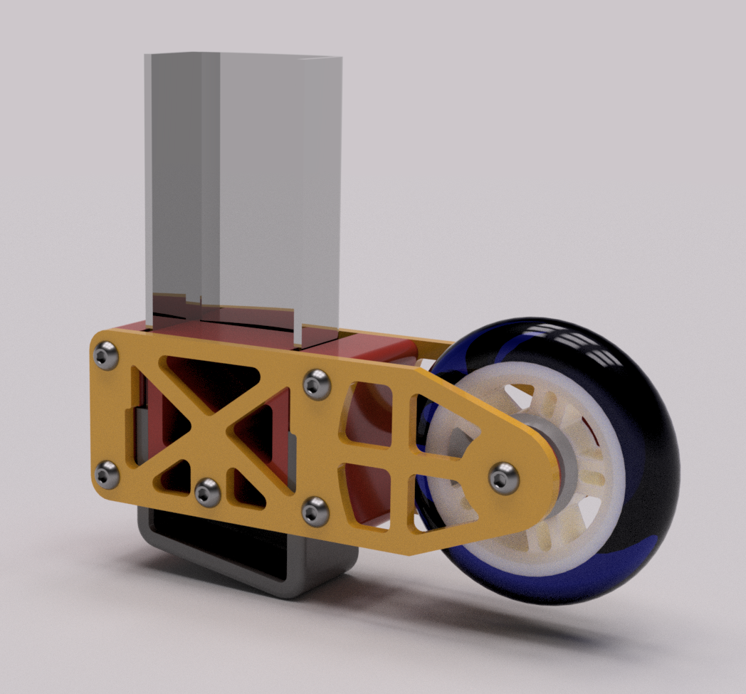
Why not have wheels on the ladder so that I could roll it outside when I needed it and not have to pick up this thing that is taller than I am in the first place? Shown above is what I came up with. I once again laid out the design using Fusion 360 CAD software (free by the way online) to get all of the parts I needed designed for the project work out. The image above shows the parts in various colors just so it would be easier to see all the different components. 


On the bottom of the ladder is a plastic foot that sits on the ground level when it is used as a step ladder. This foot is only held in place using a single 1/4" bolt. This worked out perfectly for my design as the framework of the wheel assembly needed to be mounted to the ladder and this mounting hole for the foot fit the bill. 


Inside of the wheel assembly is one of three mounting blocks (shown in red).  This is held in place using a 1/4-20 bolt 2.5" long and running through the outer wheel plates (shown in yellow) to keep the wheel assembly from moving up or down on the ladder arm. Then there are two more outer mounting blocks that again are mounted between the outer wheel plates and are on the outside of the ladder arm to keep the assembly from spinning.  Lastly the wheel that makes it all work that I found online needed to have a rounded shape as the ladder arms tip outward at the base at 7 degrees. A flat shaped wheel would be riding on it's edge so a rounded shape was called for.  I found what I needed by using 4" diameter inline skate wheels.


I started doing some calculations on the design and figured out that the ladder when you pick it up weighs 42 pounds.  But if you only pick up one end of it the weight you have to carry is only 21 pounds. So it only goes to show that each wheel only needs to carry 10.5 pounds each.  I original was thinking that I would have to make the wheel plates on the outside of the assemblies in aluminum.  I did some test parts and decided to just 3D print the entire assembly similar to what a bridge would be built like. 

Also when I 3D print parts I adjust the amount of fill I have inside the part along with the number of layers to construct it.  So if you had an egg and the shell was one layer thick to make it stronger you make more layers.  This is what I did here on this assembly.  Instead of my usual two layers I beefed it up to four layers thick and instead of making it hollow (no fill at all) I filled it at 40% fill. This make the parts very solid and with the light load I think the assembly will do the job I designed it for rather nicely. 


This is what I normally look like when I try to pick up my step ladder. Even using both hands the expression on my face is not much different than the one you see here.  (Maybe not as extreme but you get the idea).


Here I'm a much happier camper! One handed and I'm still smiling!  Eliminating 20+ pounds helps a lot. Plus the fact that now I can just roll the ladder wherever I want effortlessly! A win-win in my book any day.


I was not sure that the 4" wheels would be big enough to do the job but then again I did not want to make the wheels to large either just to make storage any more difficult in the process.  I will keep an eye on the wear and tear that the wheel assemblies take over time just as a precaution. 


Once I did bolt everything on to my ladder the wheel assemblies stiffened up very nicely so I think the design will do it's job as planned.  

By the way the ladder wheel assembly is only used to roll the ladder from place to place. You never step on the ladder with the wheels supporting it.  It's designed not to be able to work that way. When the ladder is used as normal the wheels do not even touch the ground. This eliminates the chance that the ladder would roll out of place and at the least have the wheel assembly break apart because of the extra weight if you stepped on the ladder when using it. The smile on my face will increase over the years as I use this newly designed attachment to eliminate or at least lighten the load so to speak of a back breaking chore. 


Wednesday, December 20, 2017

A Simple Project For Great Photos Of Your Projects!

Over the years I have been complimented numerous times by people who have seen photos on the blog of the projects I build and how these photos themselves look. So with that in mind I thought I would show you a very simple project that anyone can build to get the same results that I do.  In almost all of my photos of my projects, the subject is photographed so that there is a seamless white or colored background behind it.  This shows off the projects nicely and is easily achieved using a small stand made from 1/2" PVC pipe, some connectors, poster board and painters tape. 


The photo above shows the simple stand that you will need to construct for this project. Here is a list of materials that you will need to put it all together.

1/2" PVC Pipe 24" long - 2 needed (upper framework)
1/2" PVC Pipe 14" long - 6 needed (upper framework and legs)
1/2" PVC Pipe 1 1/2" long - 4 needed (upper framework ends)
1/2" PVC "T" connecter - 4 needed (upper framework)
1/2" PVC Elbow - 4 needed (Top connectors for legs)
1/2" PVC End Cap - 4 needed (Bottom of legs)
12" - 20" of Painters Tape


The PVC is cut to length using a pipe cutter or small hand saw.  Then assembled to the connectors, elbows and end caps (as shown above) to make up the stand that is pictured in this post.  No glue is needed as this makes it easily possible to fold the stand up when not in use. Just push all the parts together as there is enough of a friction fit to make it all the parts hold together and stand up easily.


Next attach a large piece of poster board to the rear cross member using painters tape. The poster board shown in the photo above is 22" x 28" in size.  This can be found at any craft store or any store that handles school supplies. I use painters tape to attach the poster board. When you have completed taking the photos you want the painters tape can then be pulled off of the poster board and then wrapped around the upper framework for later use. With the shorter edge of the poster board attached to the rear cross member the poster board naturally bends when it is resting on a table.  This makes a nice even seamless background with no ugly edges for your pictures.


This is what my subject looks like once it has been placed on the "stage" ready for photos. As you can see I have a lot of room for my little Lego Jet Man and it's and easy task to center him for pictures.


At this point, the process that I use to get the photos I want is to play with the lighting and position of my subject until I think I have what I want or at least something I can work with to edit later for use in the blog. The above photo is one that I thought would work out pretty well. 


Once I have a photo that I can work with I bring it into a simple photo editing software on my computer.  All I really need to do at this point is crop the photo down to eliminate everything but my subject. Then I adjust the lighting and contrast and when I am happy with it I call it good.  It's that simple.  It gives me a nice photo of my project so that I can show you and everyone else who reads my blog what I am working on or have just completed. The photo above probably should have used a colored background so that the white propellers would have shown up better but you get the idea for this setup anyway.

It's that simple to get good photos of your projects to show off your hard work to your family and friends or post on your own blog. Cost for the background stand for your project photos is very inexpensive (less than $10) and will last for years. So put one together for you next photo shoot. You'll be glad you did. 


Wednesday, December 13, 2017

Merry Christmas From The Tinker's Workshop


I can't believe that another year has passed so quickly and we're enjoying another Christmas season once again.  I enjoy Christmas and am very grateful to all of you who have faithfully been following me while I design and build the  projects I write about on my blog every year. You are the very special people who give me encouragement to continue working on the things that I create. I enjoy writing my blog for people like you so I can show you how I manage to make new and sometimes unusual things.  You have brightened my days over the years with the many complimentary comments that I have received and helped me with suggestions to make not so great projects better than ever.

I want to wish all of you a very Merry Christmas and a Happy New Year. I hope that the projects that you dream about, plan for, and work hard at will turn out far better than you ever imagined. Thank you all once again for another great year on the blog!

Thursday, December 7, 2017

Scrooch Gun Part 3..... It's Completed!

I am happy to report that I was able to put the finishing touches to my Scrooch gun project this morning.  Not a terribly difficult project with only a few modifications to get the kinks worked out here and there on the design. So let me show you how it all turned out.
(Click on the images for a larger view)

As I stated in my last post about this project I was not able to get the word "Scrooch" put on the side of the gun.  Simply because the lettering was way to small to get it to work out. I would have needed an electron microscope to get it cut out and then laid down the way I wanted.  At least that's the way it seemed at the time. So I opted for a simple lightning bolt in bright yellow instead. It looks to be a good choice for this 50's style space gun.


The details that show up in the photos of the gun turned out very well. I was a bit worried about the red trigger being as smooth as I wanted it to be and am happy with my efforts on that detail and it's installation.  Very clean all the way around. 

The pistol stands 7" tall and is 10 3/4" long from front to rear.  Overall weight of the Scrooch gun came in at exactly 12.5 oz.  So it has a nice solid feel to it when you pick it up.  There are only two bolts that hold the pistol grip to the body of the Scrooch gun and a threaded rod that runs through the entire length of the body to hold the canister (shaving cream can), 3D printed parts, red discs, and clear dome nozzle all together. 

The rear of the gun worked out very well also.  I like the digital display along with the red on/off switch. It gives me ideas for another pistol but next time make it actually functional. Not as a real weapon of course but as having a real digital display with a trigger that when pressed would make a space gun sound.  Then add in LED lights that flash at the front of the gun to top it all off.   All of the electronics to make it all work could be housed in the large canister that you see here or something like it.   Something to think about for sure. 


I took a load of photos this morning to get various angles of the Scrooch gun shot for this post. Out 45 photos the ones you see here are what I felt were the best of the lot.  They give you a good idea of the overall look and detail of the pistol. 


Here's another good shot of the rear of the pistol with the digital display and the on/off switch.  The digital display was simply printed on my computer printer and then covered with clear packaging tape to waterproof it.  I then glued it into the cavity you see here. Turned out better than I had hoped.  The red on/off switch I 3D printed and then sprayed gloss red. The black inset to make the on/off emblem on the switch was designed into the part and with the part being black to start I was lucky enough to have still stand out after I painted it red. 
Lastly I wanted to show off just the display stand itself that I put together for the project.  The base is nothing more than a well sanded piece of plywood that I primed and painted gloss black. The vertical and horizontal pieces that make of the support arms for the display are 1/4 aluminum rods and the black connecting parts on the support arms are 3D printed parts that I designed and made with my 3D printer. The base only needed to be drilled to receive the support arms and the arms themselves were simply super glued together. A very solid and clean looking display stand. 

That's about it for this project.  Now I will have to find nice little corner of my workroom or living room to display my latest creation.  Enjoy the photos and have a good day on your latest project.

Monday, December 4, 2017

Scrooch Gun Project Part Two

I wanted to get this post out before I make any further progress with my Scrooch gun project.  As with most projects not all things go according to plan.  This has been the case again with this project so it was no big surprise for me. Parts have taken longer to dial in and some parts needed to be totally scrapped and the list goes on from there.  But I want to show what progress has been made in the right direction to complete the project.


Here once again are the original images of my computer model for the project.  In these images I will explain what has happened and what needed to be changed.  On the rear of the gun a new display has been worked out that I feel is an improvement from what I had originally planned.  This being a digital display (non-functional) and an red on/off switch (again non-functional). The chrome inserts on the side of the gun had to be scrapped completely.  They look good in these images but turned out to be way to small to actually be built to look like the images above.  The name Scrooch Gun on the side also needed to be scrapped as this was near impossible to make on my vinyl cutter.  Super tiny would best describe the letters which made it awful to try and work with the vinyl as a decal. Other plans have been worked out for a new design for the sides of the gun.

The good news is that the red disks, clear dome front, trigger, orange canister, and pistol grip look to be right on the mark to what you see here.  So read further to see where I am with the build now.


I started this project by drilling out the center of the empty can of shaving cream. This was an easy task for my drill press and by using a small grid laid out on paper to get the positioning of the hole correct on the bottom of the can.


I then sanded the canister down to take most of the paint off of the outside before I sprayed it with a nice bright glossy orange color.


Here is the paper grid that I used on the canister and needed for the next portion of the build.


I took a plastic half sphere normally used for a Christmas decoration and cut it down to make a flatter dome shape for the front of the gun.  With the grid laid out on the drill press I was able to pinpoint where the drill would be centered on the grid and then placed the dome to match it's location to center the hole needed to mount it on the gun correctly.  This worked out pretty well and I am happy that I came as close as I did to hitting dead center on the dome.  So it was worth the effort.


 For the red disks for the gun I was fortunate enough to get my hands on a laser cutter that is now up and running at the makerspace where I teach CAD and fiberglassing.  I again worked out the files I needed for the laser cutter and in 30 seconds the parts were cut out perfectly.  I couldn't have ever cut these out by hand this nicely.  I could try but I doubt I would get this good of results. 


Here the red disks and clear dome are laid out with three 3D printed parts for the barrel of the gun along with a few pieces of hardware to tie it all together.


Here's a good shot of the barrel or should I say blaster end of the gun assembled on to a threaded rod that runs through the entire assembly to hold it all together.  I really like the red disks along with the silver painted 3D printed parts of the assembly. 

Here are the parts that make up the body of the gun. All are 3D printed and pretty much worked out as planned.  All except the one
that is in the upper right corner of the photo.  This piece took two hours to 3D print which in the scheme of 3D printing in general is not a terribly long time.  Only trouble is that it took me three tries to get it dialed in to work correctly. 


Here is a good shot of the rear of the pistol with the digital display and on/off switch painted and installed into it.  These are nice details that will make the Scrooch gun stand out when it is completed.


Another good reference shot of the 3D printed parts assembled without the orange painted canister or the blaster front mount assembly. All of these parts are held together with just two button head bolts that are mounted in the base of the assembly and held in place with two recessed nuts in cavities in the two upper mountings for the orange canister. 

I should have the pistol completely assembled in the next few days.
I will make sure to put out the final posting about it and let you see the end results.  I think you'll like it.  Until then have a good day in your workshop. 


Sunday, November 26, 2017

Lancia Stratos Blender 3D Project Pt. 4

I've managed some nice progress on my Lancia Statos Blender 3D project over the past couple of days. With this project I have learned a few new things along the way and managed to make some nice improvements with my model making.  This is always the case with working with any project I create in Blender.  Lots to learn along the way and so my models seem to improve like anything else would with practice.  So here are the latest images and progress so far.

(Click on the images for larger views)

As usual with my car modeling I experiment with lighting early on just to get some idea of where I want the completed model to end up.  But this usually changes as I progress either with different lighting that is far better than when I start out.  But at least with the images you see here you can get and idea of the potential of how the car will look once I am done fussing with it.


The model now has the wheels, tires, and glass installed but I will still need to add things like the lights (front and rear) and window trim, door handles, and the list goes on from there. The image above you can see there is no exhaust, tail lights, license plate too. Lots to do yet.


With the making of the rims and tires for the Lancia as with all of the vehicles that I have modeled I find this the most enjoyable to try and create.  The wheels really bring the car to life.  The rims that you see here are as precise as I could make to copy the reference drawings that I found online. I have showed the model to several friends of mine over the past few days and everyone says that my images look like photographs of the real car.  High praise for a Blender modeler like me.

There is a lot of detail in the tires and I was lucky enough to find an add-on for Blender from a site named Blender Market.com. that was exactly what I needed.  On this site there are hundreds of add-on's that either simplify processes to make things using Blender to having files that will add finished models to add to your creations again to save a lot of work.  This was the case for me in finding tires that fit the bill.  I was able to add tires in minutes rather than struggle for an hour or more just to create something that may or may not be exactly what I wanted in the first place.  

The rims on the other hand I wanted to be exactly what was on the car.  Not an easy task but I think I have them very well dialed in for this car. Not sure how many hours I have spent in just creating the rims. But it's a labor or love to be sure.   

So that's about it for today.  I should be able to wrap up this project in the next week or so (hopefully).  Once I get the Lancia all put together to my liking I will post the final images to let you see how it all turned out.  Also for those of you who are also into creating things using Blender 3D here is the link to the Blender Market site. Well worth your time to check out.


Have a good day on your latest Blender project!

Tuesday, November 21, 2017

Lancia Stratos Blender 3D Project Pt. 3

This week I am happy to report that I have managed to get my Lancia Stratos Blender model body pretty well dialed in.  At least I think so anyway.  I could be wrong as I usually am when I model something like a vehicle.  But at this point I think I am on track. 


I came across several things with my model that I needed to correct after pouring over the reference photos that I had collected.  One of the big things was wrong was the top edge of the body where the side meets the front hood and rear trunk surfaces.  On my first attempt this edge simply was not there.  It was more rounded and did not have this distinctive edge. I had to do some major reconstruction to get this edge that flows from the front to the rear of the car. But with a bunch of tweaking I managed to get it where I wanted it for the images that you see here. 


In the image of the rear of the car that is shown above I ran into another snag that kind of threw me for a couple of hours.  I wanted to put in the circular housings that you see in the image for the rear tail lights. When I modeled them all seemed in order until I rotated the model in Blender and then they disappeared. I rotated the model back again to it's original view where I started and the housing reappeared!  I guess I rotated that view at least a half dozen times and so I thought just blow the housings away and start again.  I did that and ended up with the same results.  Depressing to say the least.

After that I left it sit for a couple of hours as it was driving me nuts by this time and at this point I did not want to start over from scratch. I thought about it for a while and came to conclusion that I had something set in Blender wrong that caused the problem.  Sure enough this was the case.  I had a setting in the display window menu for X-Ray that was checked.  I unchecked the selection and low and behold everything was back to normal!  Blender can do that to you once in a while and even though I have 15 years experience with the software it still happens to me on occasion.  So I am happy with the body of the Lancia so far and look forward to start work on the wheels next.

I also have to figure out what I want to do with the car once it is completed.  Most of my vehicle models are just the cars or trucks by themselves.  I will have to work on some kind of setting for this car and another one or two that I have on file.  Something else to think about to complete the model. 

Anyway I'll keep you posted with my progress in the coming weeks and have a good day with your latest Blender project too!

Thursday, November 16, 2017

Lancia Stratos Blender 3D Project Pt. 2

With some nice quite time today I was able to make very good progress on my Lancia Stratos Blender 3D project.  This is a challenging vehicle to model and I still have some tweaks to make on the body as you will see in this post today. 


(Click on the pictures for a larger view)

The lines of the body came together pretty well after working with the Blender model you see pictured above for a couple of hours today.  I like the door seam and the beltline(?) that runs along the body across the door and the rear panel just behind it. As usual with my vehicle Blender creations I collect a lot of photos from the Internet to use as reference material. 

I have found with this vehicle that some of the reference photos are not of a real car but are of toy models of this car.  This is very evident when I find a wiper blade in the photo that looks to be as big as my arm compared to the rest of the vehicle.  With finding this type of photo I immediately dismiss it's accuracy as I want my Blender model to be as close to the real thing as possible.  Needless to say I take a very close look at the little details in my reference photos to get my Blender model where I want it to be.


With the view  shown above I was happy to see the reflections of the door and the rest of the body match up very well.  It will be interesting to see the windshield in place to fill the void that is now in the body shell at the front of the model.  What really brings the car together is the wheels but at this point I have some ways to go before I can get to modeling them.  I just will have to keep plugging along with my efforts and check and recheck my reference photos until I am happy with the finished body. 

One big fun puzzle just like all the rest of the vehicles I have created so it is a good thing to work on when the weather outside is far from ideal to do anything else. Hopefully I can finish at least the body work by the end of the weekend.  I'll keep you posted as I move forward with this fun project to let you see my progression in it's modeling.  Enjoy the pictures.

Wednesday, November 15, 2017

Becca's Bathtub Project

The last couple of weeks have been nothing but run, run, run.  I am sure all of you have had weeks like this but with my running I have gained new friends that have wanted my assistance in helping them with their projects. As many of you already know I am helping out at a new makerspace in Dubuque Iowa named the Key City Creative Center.  Along with my helping with projects I have been teaching computer aided design, fiberglass class and soon will be teaching CNC machining. On top of all of this I am on the board of directors for the center.  


So that brings you up to date on just the background of my post today.  Now on to what the heck is "Becca's Bathtub"?  Becca Kacanda is a very nice lady who is a member of the makerspace and that I have been getting to know and help with her very interesting project.  Becca is an artist in her own right who has been given a grant to created a piece of artwork for a showing some time next year.  Her original work involved a very heavy cast iron bathtub. She had taken the old tub and cut it in half and then decorated with various bits and pieces of varying materials to create interesting designs on the tub. Everything from pennies to broken mirrors. Even with the tub cut in half it takes three men and a monkey in order to move the completed artwork even just across a room.  (By the way the monkey is needed to give directions.)  

Anyway Becca had taken my fiberglass class that I teach at the makerspace and I suggested to her to make the new piece of artwork out of fiberglass instead of having to deal with the old cast iron tub.  She thought the idea would be perfect for the project and so I have been helping her with the design and construction of the new tub or should I say enclosure now.  The enclosure for a lack of a better terms for this form will be made of a foam and fiberglass composite construction and when completed Becca will be able to easily pick it up one handed!  Plus the fact that the new tub will not have to look like an old converted cast iron bath tub when it is completed. 


I had worked out several different designs for Becca and she settled on a more modern shape to get things started.  


I worked out the design for the new enclosure using Fusion 360 cad software.  As I said earlier in this post the construction will be a foam a fiberglass composite which makes things quite simple to build.  In the image above you can see the layout of all of the pieces along with a temporary stand to hold all of the ribs in their correct locations while the structure is being built. 


I colored all of the various pieces of the framework differently in the images above just to show where everything goes when construction begins.  This helped Becca and I keep things in order while we were putting it all together.  The extrusions on the back of the enclosure will be cut off before the outside of the structure has been covered with Styrofoam strips.


Here's Becca fitting up the Styrofoam strips for the interior of the structure.  She and I had spent five hours tracing out the templates for the parts on to a 4 X 8 sheet of Styrofoam and cutting all of the pieces out the day before.  After this was done all the parts had to be hot glued together to make the shape that she had decided on for the project. As you can see the shape is coming together nicely.


The foam strips that we cut from our Styrofoam are 1/4" thick, 1" wide and 4' long.  Becca is taking each strip at this point and cutting them to length, sanding the edges smooth and test fitting them so that they can be hot glued into the interior of the enclosure.


Lot of cutting and trimming needs to be done to complete this project.  Becca's is still wrapped up to stay warm as the shop had not been warmed up yet when she started working the night I took these photos. 


The strips of foam are hot glued in place and each need to be hand fitted to cover the interior of the ribs for the new enclosure.  With each piece that is added the structure gets stiffer and stiffer which is a good thing but over all it is still quite fragile.  Once we get into laying in the fiberglass to cover the structure inside and out it will be well protected, strong and very light weight.  The new structure will be a custom design and be light enough to easily be moved from one place to the next. 

As Becca's Tub project progresses I will shoot photos to show you how it all goes together along with the details of what Becca has planned for it's final artistic look.  I'm sure it will be quite interesting to see the end result when she is done with the project.