Saturday, August 31, 2013

TerraTrike Velomobile Blender Image Variations

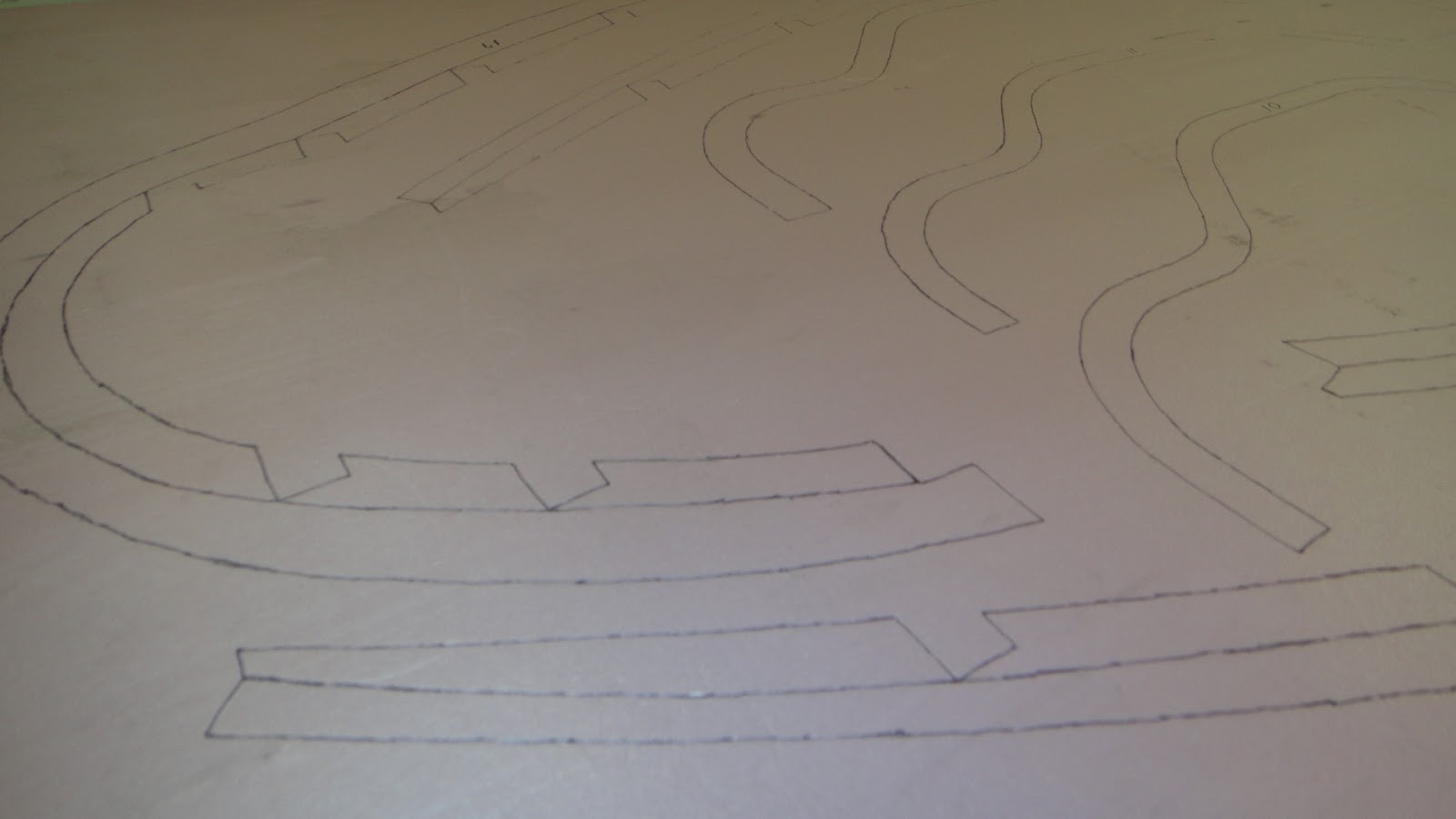
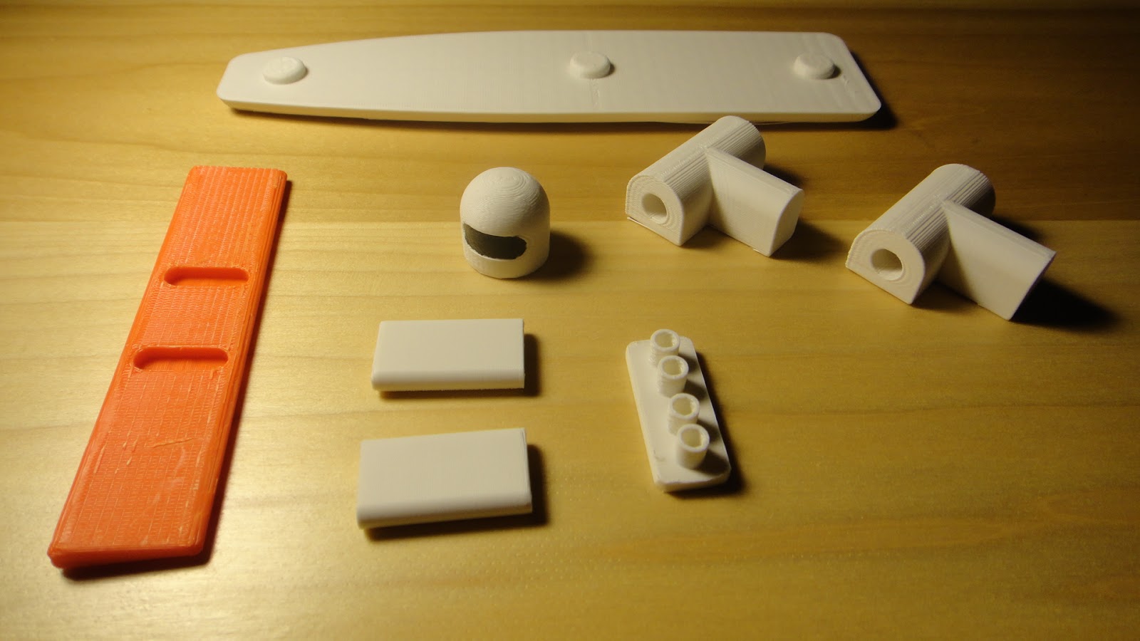
The past couple of days here in the Midwest have shown it's true colors once again with August heat that is the norm for this part of the country.  Late in the season I think but still it's August and it's hot.  So to keep busy I have been doing work on the velomobile project that does not require fiber glassing and so I managed to get the 1/4 inch foam strips cut for the body of the trike which will be used to skin the body like a cedar strip canoe.  This did not take as long as I thought it would and so I went on to looking at variations for my design using Blender 3D software.  
  For those unaware of what Blender 3D is all you need to know is that it is a creative way to make 3D graphics, animation or video games on your computer.  The plus side to this great software is that it is free and anyone can download it online.  The minus side to the software is that it will take you some time to learn how to use it.  But don't let this discourage you as there are tons of tutorials and Blender user groups online to help you get started.
  Anyway yesterday and today I have been putting together Blender images of variations on my velomobile design that I am now building. The reason behind all of this came about with a discussion with my brother about my design and the fact that it is to large to be completely built in my basement workshop.  The project now resides in my garage and is on hold until the weather gets a bit cooler.  So here is what I came up with.


 This is a great view front of my TerraTrike Velomobile that I created using Blender 3D.  I can only hope that I will be able to get my project to look this smooth when I am finished with it.  A goal to reach for that is for sure.


Here is what the back of the velomobile will look like.  I still want to figure out a tail light and possibly a signal light set up for the project.  Also what is needed is rear view mirrors.


This is where the variation on the design comes in.  Behind the driver is a protrusion that comes up to the middle of his (or her) head.  The original design is shown in front.  The next design has a smaller protrusion and the last one has no protrusion. 


With the design having a smaller protrusion or no protrusion at all makes it possible for me to build the entire project in my workshop and still manage to slide it out of a standard doorway when it is completed.   Just not 100% sure I want to change the design at this point just so I can slide it out of a doorway.  Another feature that I will put into the velomobile is the blacked out dash and the mounting for my GPS display.  This mounting will allow me to remove the GPS when I need it in my car or I want to keep it from being stolen from the velomobile if I should have to leave it parked unattended.


This view of all three designs shows off the variations of having or not having a rear protrusion on the vehicle.  I will also have to work on making the wheel covers for all of the wheels.  I suspect that these will either be made of light weight plastic or fiber glass.  Just will have to see what I can do when the time comes to putting them together.  Another project within a project so to speak.  
  I am also playing around with the idea of have the velomobile fully enclosed for cooler weather driving.  Just have not gotten that far with the design yet as there are to many other details that need to be worked out to just get it on the road.  If I did fully enclose the velomobile the roof structure would be removeable so that the configuration that you see here could be used in warm weather.
  Let me know what you think of the variations on the body design.  I  would very much like to hear your opinions about what I am working on.  Enjoy the Blender images!

Tuesday, August 27, 2013

TerraTrike Velomoble Project On The Jig

With all of the hot weather we have been getting this past week or so I was surprised that I was able to get the velomobile into the build jig today.  I finished sanding all of the ribs for the build after a couple hours work and then slide everything into the jig to get the photos you will see here.  That was about all I could do as the garage was like a sauna this afternoon. 


I slid the ribs into place and then started scratching my head as to what pieces should be set up next.  I am so happy that I had the computer model on my computer to see how it all will go together. 


This is a great shot of the nose of the velomobile.  As you can see the ribs are not exactly squared up yet but I wanted to at least get these photos taken to show you how the project is coming along. 


 The ribs all slid into position fairly easy.  The only tweak I had to make so far with the jig was the slots that I had made for the two front ribs. They were not cut to the right depths.  This was an easy matter of laying out additional cut lines and pulling out my jig saw.  After I had done only this little correction I had to call it a day due to the excessive heat that was in the garage. Temperatures today reached 94 degrees and I think the garage was closer to 100.  Just to hot to work even if it was this fun project. 
  The middle of the body with the short ribs on top will be where the front wheels of the TerraTrike will go.  I will  have to slide in side members into all of the frames on both sides and then add additional pieces that will form the fender wells for the wheels. 


Once the framework of the body has been completed it will be pulled off of this jig and then be set up to be skinned and fiber glassed.  I will probably have to modify this jig so that the framework skinning can be completed on it without having to lay the body on the floor. I will just have to see what I can come up with when I get that far along. 


  Here the TerraTrike sits next to the velomobile body jig.  One really good thing about the build is that the trike will not have to be anywhere near the body while I am doing the fiber glassing.  This will keep it from getting messed up in the process of the build.  That would not be a good thing to happen.  On the floor next to the jig you can see the two main stringers that will be mounted to all of the ribs to hold the assembly together.  It will be a job to put these two large pieces into the assembly but once done it will add a lot of strength to the framework and keep everything nicely aligned.
  I will have to wait for the temperatures to return to normal here at the workshop before I can proceed with any fiber glassing. It is just to hot at this point to even think about it.  In the mean time I will tweak what I have to and keep things moving along.  Hot or not I am a happy camper with the progress that I am able to show you today.  Have a good one and check back when you can to see further progress. 

Sunday, August 25, 2013

TerraTrike Velomobile Light Weight Parts And Build Jig

The last couple of days have been kind of hectic here at the Tinker's Workshop with the continuation of the building of the TerraTrike Velomobile project.  In my last post I had completed all of the fiber glassing of the ribs for the body and cut them all to size.  This was a big task in it's self so the work progress over the past few days with the sealing of the cut edges on the ribs has been keeping me busy.  This was needed to be done so that the exposed foam could be protected against the elements and time and the parts and project will last longer because of it.  


This strange looking tool is called a hot knife or loop I don't recall which but it is worth the cost of the tool as it saved me a tremendous amount of work by being able to remove styrofoam quickly and easily.  The tool is plugged into a transformer and electricity flows through the loop of wire and heats it up.  This in turn makes it easy to melt styrofoam like a hot knife through butter.  The loop of wire on the end as you see it I formed into a special shape so that it would remove only about a 1/4 of an inch of foam from a fiber glassed panel. (See the next photo)


 Here I used the tool to start removing some of the foam from one of the ribs for the body.  I simply run the wire along the inside of the parts and move it along until I have removed what foam I want taken out. 


Once all of the parts have had the exposed foam removed that was not needed I then mixed up batches of fiber glass resin and micro-ballons (microspheric hollow glass balls) to form a putty that replaced the styrofoam with a permanent seal.  The putty mixture is cured over night and then sanded to a  smooth surface with sand paper.  This makes a very strong seal and actually makes the part stiffer as well. 


Here more of the ribs are set aside waiting to be sanded smooth.  The white putty mixture really brightens up the parts.  Some of the piece you see here are not fully sealed with the putty mixture as the center section of the foam on the lower portion of the parts will be removed in the final assembly of the framework.   The outer edges of all the ribs will have the skin of the body mounted to them so it will protect these edges as well. 


As you cane see with these two parts there are a wide variety of shapes that are needed for the TerraTrike Velomobile project.  I took all of the ribs at this point in the build and weighed them. The total weight only come up to 9 lbs 2.3 ounces!  I am very happy to find this out as I am right in my guess of the weight of the body.  This total weight of these parts will decrease as I do more finish sanding on the parts and do the final trim of exposed foam sections on the ribs. I suspect that the total weight of the body will be around 20 pounds or so.  So it is looking good so far.


A rather strange looking assembly that I needed to put together was completed today in the shop with a bunch of scrap lumber I had laying around.  This assembly is the build jig for the body.  Or at least the first jig that is needed to get the ribs into their correct locations for the build.  The blue panel in the computer image is a temporary 4 x 8 foot foam panel that is cut with notches so that the ribs can be slid into correct placement for assembly into the body of the velomobile. 
   Once all of the ribs have been connected together the body will be removed from this jig and permanent pieces of foam will be mounted into the framework where the blue panel was originally.  This will make more sense once that portion of the assembly is photographed and I can show you in a later post.


 Here is a couple of good shots of the jig in my backyard.  This jig is a little over eight feet long and needed to be moved to my garage where the final assembly of the velomobile will be completed.  The workshop is large enough to build the velomobile in but the doorways from the shop are not large enough to get it out of the shop.  This is why the project will be moved to my garage where there is sufficient space to complete the project and get it mounted to the TerraTrike.
  As you can see a lot has been done on the project in a very short time.  Total hours has now come up to 147 hours.  But again I must remind you that about 100 hours of this time was just in the designing of the velomobile.  So 47 hours for all of these parts plus the jig is really not to bad.  Should get really interesting once I can start putting the ribs into the jig and you can see the body starting to take shape.  This will have to be put on hold for a few days as it has managed to get rather hot here again in the Midwest with temps over 90 degrees again predicted for the next three or four days.  By then I should have all of the ribs smoothed out and ready to go so check back again and see how I'm coming along with this fun build. Have a good day and keep tinkering!

Thursday, August 22, 2013

TerraTrike Velomobile Parts Are Stacking Up!

  I have been laying a lot of fiber glass and making a lot of dust in the workshop while working on the TerraTrike Velomobile project this past week or so. In the last post here on the blog I laid out about half of the parts that are needed for the main structure of the velomobile.  These parts were then set aside for the remaining set of parts for the framework that needed to be fiber glassed.  Once all the parts had cured and been glassed on both sides of each of the 4 x 8 foot panels I could start cutting the parts out. 


  The easiest way that I found to cut the parts out of the large foam panels was to use a hand held jig saw. This made short work of being able to get individual parts from such a large panel.  I did not worry at this point about making finishing cuts as this would come later after I had all the individual parts stacked up.


 This was the first stack of scrap that I was able to get rid of after doing the rough cutting of the panels. Some of these foam pieces are still useable and so a little sorting was called for at this point before I declared the rest to be scrap.


  Now all of the parts have been trimmed to a more manageable size to be ready to be fiber glassed on the back sides and later to be trimmed using the band saw and jig saw.  Only about half of the parts needed for the project are shown in this photo.  This was only the first panel of parts but it gives you the idea anyway as to how much I was able to trim out of the panels.


This photo shows all of the parts after they had been cut to correct size using the band saw and a jig saw.


A couple more views of all the trimmed parts for the framework of the velomobile are shown here once again. Everything is numbered so that I can keep it straight when it comes time for the assembly of the framework.  
  I am very pleased with the way the parts turned out.  I spent another 20 hours or so on the project to get to this point. This brings the total hours to 130 and counting.  Not sure how many more hours until completion so I will just have to just keep track to see how it all stacks up. Assembly cannot start just yet as there are a couple more steps in the process that need to be done next.  
  All the parts shown here have now been fiber glassed on both sides and cut to correct size.  The cut edges are exposed styrofoam.  About half of these exposed edges will need to be protected with a layer of epoxy resin and micro balloons.  
  Micro balloons are microspheric hollow glass balls and it looks like talcum powder but is very very light weight.  If you threw a handful of this stuff into the air it would float like smoke. It is that lightweight. This powder is mixed with the fiber glass resin to make a putty. Some of the styrofoam is removed from the exposed edges that you want to protect.  The void left by the removal of this styrofoam is then filled in with the micro balloon mixture and left to cure.  It then leaves a solid surface that will be sanded and painted and will seal up the parts perfectly. If you do not protect the exposed styrofoam it will degrade over time and then your parts or worse yet your entire project will be junk.  I will be posting more about this process once I get that far into the build.


Here is the second pile of scrap from the final cutting of the parts for the velomobile. None of this foam is any good anymore as it has served it's purpose well.  Just to do the final cutting of the parts took about four hours.  But in the end the band saw and the jig saw have paid for themselves once again. Another good day at the Tinker's Workshop.  

Friday, August 16, 2013

TerraTrike Velomobile Fiber Glassing Has Begun


After having spent over seven hours tracing out the parts for the TerraTrike velomobile project I thought it best to keep pushing on today and get started on the fiber glassing of the parts on the first foam panel.  This again is not a difficult task to do. As with the tracing it all takes time and a little effort. 


 In this first photo you can see some of the strange looking shapes that will make up the framework of the velomobile body.  In the upper left corner of the photo you can see the fiber glass cloth that I need for these parts.  Lots of little piece of fiber glass cloth was needed to be laid into place over the traced shapes.


 The three curved pieces in this shot will be part of the framework that will be located just ahead of the driver (namely me) when I am sitting in the vehicle. (See first photo in this post)


This large center piece in the photo will be the part of the frame that is just behind the driver in the velomobile.  All of the parts have several layers of fiber glass cloth on them at this point.  I will let these cure over night and then cut the panel up into smaller more manageable individual parts so the back sides of the parts can be glassed again. I will try to eliminate as much unneeded foam during this step to save materials for the glassing of the parts.  Once this also has had time to cure I can make the final cuts to clean up the parts using my band saw to get them to their correct shape for the next step in the assembly. 
  I will have another complete panel of parts to glass the same way that you see here and then a few more steps in the process before I can set up a build jig so the body can start to take shape. 
  For now I am happy that I am able to get to the glassing of what you see here and I am able to get some decent photos to give you an idea of all the different pieces that will be needed for this project.  
  To give you an idea of the weight of these parts you should know that a 4 x 8 foot sheet of styrofoam only weighs around four pounds.  As I am cutting a lot of parts out of one sheet and eliminating a lot of wasted foam you can see that these parts will be very light in weight even with the fiber glass on them.  It will be interesting to see how it all comes together.  
  Three more hours work on the project today brings the total up to 110 and 1/2 hours. (Roughly)  One step at a time and before you know it I'll have the frame ready for assembly.
 

Thursday, August 15, 2013

More Recumbent Velomobile Parts Layout

After acquiring a good case of writers cramps I had completed the parts layout for the recumbent velomobile project.  I spent four hours today getting the third panel of parts set up from the full size drawings that I had completed weeks back.  This is the last of the 26 parts that I will need to trace onto the 4 x 8 foot styrofoam panels. Not a hard task but one I am glad to complete.  


This was my road map to place parts on two of the foam panels.  I worked this all out on my computer before I started and I'm glad I did as even with this map it was like a jigsaw puzzle to get all the drawings to lay down correctly so that I did not have any overlapping drawings once everything was traced out.  


Here my workbench is starting to look like my old drafting table when I had a lot of work piled up on it.  I will stash these drawings away if I should have to make repairs or if I want to build another body for another trike in the future. 


Here the largest drawing was laid out on the styrofoam.  This piece is like the keel of a boat.  It will be the main jig of the velomobile trike body structure.  The panel has a series of slots cut into one 4 x 8 styrofoam panel that position the ribs correctly while the body is being built.  The simplest part to make and the biggest.  This part I will not have to fiberglass as it is only a temporary part to hold the ribs of the body into place until they skinned with styrofoam like a cedar strip canoe and are glassed together. It will make more sense once I get that far into the build and you can see it all set up. 


Another big part for the velomobile trike project.  The curved drawings took longer to layout as I had to mark everything by hand.  


These photos show some more of the body parts laid out on the styrofoam and the complexity of the final structure.  I will fiberglass these parts on one side next.  Once this has dried I will do a rough cut of the parts so that I can glass the bottom side of the pieces.  Again once these have cured I will do the final cut out of the parts to get them into shape.  
  I figure to get the parts glassed and cut out will take me four days time.  This mainly because of the time it will take the fiber glass to cure. Total time to just transfer the drawings to the styrofoam comes up to seven and a half hours.  The amount of time to do the design work on the body I would suspect comes in at around 100 hours.  
  I'll keep a running tally of the total hours and the cost and let you know when I get this project put together.  A good step forward with the completion of this process of transferring drawings  now on to the next step of the build.

Wednesday, August 14, 2013

The Recumbent Velomobile Project Moves Forward!

Today had a bright spot in it for me as I finally got an order of styrofoam delivered to the shop so that I could start work on making parts for the construction of the body to the recumbent velomobile that I have posted about weeks back.  
  With this order of foam I laid out most of the components for the body today.  This is a simple process of taking full sized drawings of each part and tracing the drawing while it is position on the foam panel.  When you trace the part an indentation is created on the foam and then you go over this indentation with a Sharpie or some similar marker so that you can see it better when cutting parts.  Once I have all the parts marked out on to the foam I will fiber glass the panel, let it cure over night and then cut it apart.  I then will turn the parts over and glass them again on the opposite side.  This will make nice light, strong parts for the frame of the velomobile body.  Once all of the glass has been laid down and cured properly the parts will be cut again to trim them down to their proper shape.  This is the same process that is used in the construction of experimental composite aircraft.  I have used this technique when I built my three piece take apart kayak and my cargo trailer for my motorcycle.
  Not wanting to waste a perfect opportunity to have some fun and document what I managed to get done today I set up my handy dandy Ipad with an app to create a little time lapse video.  I compressed the 3 1/2 hours of work in the shop to just about 2 minutes.  It's a fun way to show you the process of transferring the full sized drawings to the foam panels and test out the app at the same time.  


I'll be posting more info about the recumbent velomobile project as I get farther along with it.  Until then enjoy the video. 


Saturday, August 10, 2013

3D Printed Indy Racer

  Following with my train of thought about vehicles for the past couple of weeks I completed this neat little 3D printed Indy Racer this morning.  This design I had in my files for some time with a couple more ideas that will be coming in the future on the same line.  My original thought a couple of years ago was to make a series of toys that used skateboard wheels as the main focus of the design.  This is the case with my little Indy Racer that you see here.


The racer is 8 1/2 inches long, 5 1/4 inches wide and 3 1/2 inches tall.  Other than the use of the skateboard wheels it was completely printed using my Makerbot Replicator 3D printer.  


The body of the racer took the longest to print as it is the largest piece in the assembly.  It was printed all in one piece and took 7 1/2 hours to complete.  I am very pleased with how it turned out.


Here is a photo of one of the wheel/axle assembly parts.  It uses two standard skateboard wheels complete with bearings.  I found a complete set of four with the bearings on Ebay for $10!  The bolts are 2 1/2 inch long 5/16th inch bolts.  These were a perfect fit for the bearings.  The "T" shaped part is the axle housing and the two little cylinders are spacers for the wheels.  


Here one of the wheel/axle assemblies have been put together.  The holes in the wheel/axle housing is the perfect diameter to screw the bolts into place to hold the wheels on securely.


Here are the rest of the parts for the racer.  The top part is the belly pan of the car. Protrusions on this part were designed into it so that alignment to the body would be easier.   On the left is the rear wing.  Moving to the right is the drivers helmet and the two rear wing struts.  Farther to the right are the two wheel/axles housings and the last part with the four tubes standing vertically is the exhaust for the racer.


This is a good exploded view of the wheel/axle assembly and how it is installed into the racer.  The "T" wheel/axle housings slide into mating recessed areas in the underside of the body.  Once these are in the place the belly pan of the racer was epoxied into place to hold everything securely.  You can also see in this image the recessed areas in the body and the wheel/axle housings.  These mate up to protrusions on the belly pan so all the parts will line up properly when the the racer is assembled.
  The little racer is fast on the floor and with the skateboard wheels I would not be surprised at all that it will roll down a city street at a good clip.  More toy projects using skateboard wheels will follow with the successful completion of this little Indy Racer.  The files for this little racer are available now on my plans page for only $3.00 so that you can print your own Indy Racer for your little boy or girl to play with.  For me it will be another nice addition to my own collection of toys.
 

Check out this time lapse video I put together of the body printing for the Indy Racer.  The actual time the body took to print was 7 and 1/2 hours.  This video compressed it down to 52 seconds.  Fun to watch.  Enjoy. 

Wednesday, August 7, 2013

New Artwork Of My Dream Car

  This past couple of weeks I have not been able to create more dust in my workshop simply because I am waiting for supplies to be delivered for the velomobile project that I've posted about previously.  So with that not happening at the moment I spent some of my free time in other interests such as going to Oshkosh Wisconsin to see the Experimental Aircraft Association convention.  I have been to this convention at least a half dozen times over the years and it is always an interesting thing to check out.  Other than the air show itself and all the planes that come and go I came across the Ford Motor Company pavilion.  To my surprise parked outside were three Ford GT cars in all their splendor.  At this point a B52 could have dropped a bomb on the field and I could have cared less.  This was my dream car.  With saliva drooling down the corner of my mouth I got to see my fantasy car up close an personal.  Needless to say I just had to shoot some photos of my favorite one of the group.


Of the three Ford GT's that were there this car was calling me.  I was able to get this photo and a few more views that day at Oshkosh without a crowd of people standing in front of it.  The other two GT's were just as nice but in blue racing colors and one in white.  My rule of thumb when it comes to sportscars is the only color that counts is red.  
  So after having spent some time with my dream car and getting a good sunburn from the day in Oshkosh I trudged back to my car and headed back home to my quiet little town and the workshop once again.  I found out that I had walked nine and a half miles through the day and I was ready to put my feet up to call it a day.
My mind kept going back to my dream car. I knew I just had to create a new drawing of it.  This is what I came up with.


This drawing of the Ford GT turned out very well and some day when I win the lottery or one of my old rich uncles passes away and I inherit a fortune I will be able to buy one.  This is not at all likely as I don't play the lottery and I know for sure none of my relatives have anywhere near the money I need for such a vehicle.  For now I will just have to be happy with the fact that I got to spend a little time with my dream car and I have a nice drawing to show off to all of you reading this post. Like anything else in this world it is nice to have a dream and to just come close to touching it from time to time makes life worth it all.  Enjoy the drawing and keep tinkering. 

Friday, August 2, 2013

Blisters! Just What I Need!

While continuing work on the TerraTrike recumbent body project or velomobile as they are known over in Europe I came across another puzzle.  I put a full sized figure into the computer model of the velomobile just to see how it would look.  To my surprise I find that I still need to do a bit more tweaking on the design.  


Here is a good shot of my little man inside the velomobile.  Looks pretty good until you take a closer look at where his feet end up.  


 In this closer shot you can see what I am talking about.  If I build the velomobile as I have it designed here your feet would end up striking the underside of the top section of the body.  Not a good thing to be sure.  I am more than happy that I find this kind of stuff out while I am still messing with the computer before I get this far along in the real construction and have to make major changes to fix it. 
  The green arcs on the ribs that you see also in this close up view are what I will have to change on the both sides of the ribs before I start construction. This will give me two inches of clearance for my toes while I am driving the vehicle. The skin will only be 1/4 inch thick composite so it should give me the lightness and strength that I am looking for in the design.


The reason I originally wanted a human figure in my computer model was to see if an enclosed roof could be added to the design. The enclosed roof would be removable so that during hot weather it could be taken off or added for cooler weather.  This idea is still just a thought and I will have to play with it more once I get the new body blisters dialed in for the design. The image above turned out better than I had hoped with the addition of the blisters.  Still looks nice and smooth.  So as you can see blisters can be a good thing. I'll keep plugging along with the design. You keep checking in from time to time to see how it all turns out.  Have a good day tinkering!