Friday, October 24, 2014

Recessed Computer Monitor Desk

As I get older I find some things in my life just a little more than irritating. Not with life in general but with the fact that I am getting older and my body is not as young as it used to be.  I will be celebrating my 61st birthday in a couple of days and with my advancing years comes things like aching legs from to many hours in my workshop, to my eye sight that I will have to correct once again with a new pair of bifocals. So the project that I completed today will help me eliminate an eye problem that I have been putting up with for some time now.  With having to wear bifocal glasses it becomes a problem at least for me when I try to read something at the top of the screen on my computer monitor.  See the photo below.

                                
Here I am as usual having to crane my neck to see the top of my computer screen clearly while wearing my bifocal lens glasses.  Sure I could raise my chair so I would look more straight ahead but then I am so high up it makes it difficult to type anything on the keyboard.  


After doing some research online I came across something that I thought would work for my problem.  These computer desks are set up so that the teacher and the students can see one another over top of thier computer monitors which are recessed into the desks.  Anyone using this type of desk has to look down to view the monitor.  Perfect for what I need!


I immediately went to work using my CAD software on my new modifications that I wanted for my desk.  I could not modify my original desk top as it would have been more difficult to complete than starting from scratch.  So I would make what you see in the image above.  The monitor after having removed the stand it is normally mounted on would rest in a cavity built into the desk top and still be able to use the original platform for the keyboard and mouse. The trick was making the cavity fit in between the rails for the sliding keyboard platform. 


I started with the triangle pieces for the desk cavity as I thought they would be the toughest to make.  I was luckily wrong in assuming this as in no time at all I had what I needed for the project. I put more than enough pocket holes in these parts but I thought it best for a little overkill to rule out any chance of structural failure.  Not a good thing to see you computer monitor come falling through your desk.  


Here the desktop is assembled.  I cut a large section of the aspen wood panel and then attached another piece to it to make the opening for the desktop cavity.  Notice how the opening is not centered. This had to be this way to mount correctly into my "L" shaped computer desk and allow the platform for the keyboard and mouse to work correctly. 


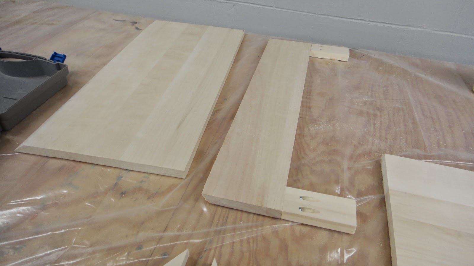
These two pieces make up the inside of the desktop cavity.  The "C" shaped piece will be used for the back of the cavity and the other piece will make up the base of the assembly. Both of these parts needed to be cut so that the edges would fit flush with the undeside of the desktop.  Thirty-five degree angles on each  to be exact.


Here the triangle pieces for the cavity are being lined up for assemlby to the face down desktop.  


A special clamp from the Kreg company is used to hold the triangle pieces in place until the mounting screws can be installed.  Kreg makes the jig that makes putting in pocket holes a simple task and is a great tool for this type of project.


Next the base board is attached to the assembly using wood glue, screws and pocket holes.  At this point in the project I am more than happy that everything is lining up nice and straight.  With the pocket holes on the inside of the cavity the outside of the desktop looks really good.  The pocket holes in the rear will not be seen once the assembly is installed back into the desk.


 The last piece to be assembled is the back board for the desktop cavity.  This is glued and screwed into place like the other parts already assembled.  This cavity needed to have this opening in the bottom rear of the assembly to allow for the cables to run the monitor to be hooked up.  I was glad that I made such a nice large opening for this task.  Makes things a lot simpler to assemble as well as use.


The next step in the assemble was to varnish the desktop with three coats of polyeurathane.  This was a simple task and only took a couple of days to get a nice clean smooth finish.


To mount the desktop to the legs of the table I needed to install the threaded inserts that were in the original table top.  I removed these inserts and then used a 5/16 drill to make the holes needed for the installation of them into the new desktop.


I placed the assembled desktop onto the leg assembly of the desk and then marked where I needed to drill for the threaded inserts.  The trick here was not so much marking the holes but drilling them.  The assembly at this point is kind of large and awkward to handle while trying to drill holes using my drill press.  I took my time and as you can see the installation of the threaded mounts turned out perfect.


I also marked the mounting holes for the platform for the keyboard and mouse while I had the desk upside down.  It was then just a simple matter of screwing this assembly to the underside of the desktop.  The clearance for this assembly and the desktop cavity was close but not impossible to make work. Not a hassle to get put in correctly.


Here the new desktop is resting on my kitchen table.  The desktop measures 27 x 33 inches and is nice an solid. 


I had filled the pocket holes on the triangle cavity pieces with wood putty before I did the varnishing just to see it it would look ok.  That is the word for it.... it's just ok.  So I went with plan "B" for this portion of the build.


I lined the inside of the desktop cavity with a some vinyl carbon fiber that I had left over from an earlier project that I had made.  The installation of the vinyl gives the desk a really nice finished look and was not really difficult or time consuming to install.  A great look to be sure.


Here is the section of the desk that will receive the new desktop.  Luckily the legs of the desk stand up by themselves and so getting everything to line up properly was a piece of cake.


This is one of the flanges that or on the top of each leg of the desk.  Machine screws are inserted through the holes in the flanges and then into the threaded inserts on the underside of the desk that I and installed earlier.


Here the new desktop is ready to install.  I placed the new desktop into it's correct position and the mounting hardware slid right in nice as could be.  No fuss at all.


With everything hooked up my computer is back up and running again.  All I had to do is place the monitor into the desktop cavity and plug in the cables through the slot in the back.  Very simple installation to say the least.


This gives you a much better idea of how the project looks while being used.  It was another great project that I've been wanting to do for a very long time and will be a pleasure to use for years to come.  Now I can let the dust settle once again in the workshop and give my neck a rest as well.  Oh and by the way I'm getting my eyes checked for new bifocals next week.  Enjoy the photos and the post.

Tuesday, October 21, 2014

Interesting Velomobile Graphic!

A couple of days ago I received an email from Mads Phikamphon  from Norway who runs the Cykelvalg website.  He contacted me weeks ago about information that he needed for a new velomobile graphic that he was working on.  Mads asked me several questions about my Radius T-T velomobile that I have completed this last summer and have numerous other posts about on the blog here.  He informed me that the velomobile graphic was completed and so I thought I would pass it along to everyone interested here on my blog.

This image is as large as I am able to post here on the blog so it will give you a good idea as to how large this graphic actually is.  To get a good look at what Mads has created check out his website I have listed below.  Interesting to look at along with a lot of other links to other velomobile builders.

http://www.cykelvalg.dk/velomobiles/

Tuesday, October 14, 2014

Custom Built Fiber Glass Coolers

I was going through some files on my laptop that I normally only use for running my 3D printer when I discovered a folder with a couple of projects that were never posted on my blog.  One of these projects that I  thought I would finally post about today was a set of custom built coolers that I had designed and built for my motorcycle cargo trailer.  Sadly as a lot of you already know the cargo trailer along with a lot of other great projects along with my motorcycle were destroyed in a major fire a couple of years ago.  This also was the case for the custom coolers that I am showing you now.  So let's take a look at what I put together way back then.


I wanted a set of custom built coolers that would fit into my newly designed and built motorcycle cargo trailer.  A standard cooler would have worked fine but I wanted something just a bit more in keeping with the design and function of the trailer itself. The first photo you see here is just the start of the coolers.  Very simple one inch Styrofoam box construction. The boxes were first fiber glassed on one side and then hot glued together. A fiber glassing resin and micro-balloon powder was combined to make a putty mixture to fillet all the inner joints.  You can see this white putty in the inside of the boxes in the photo above.  The boxes by the way are 17.75 inches by 15.5 inches by 11 inches tall.  This makes the interior of each box 1.23 cubic feet.  Nice big coolers.


I wanted a basket inside each of the boxes to hold items such as sandwiches, cookies, etc. to stay cool but not get wet by sitting on ice.  I found the baskets at a local office supply company that fit the bill perfectly.  To hold the baskets in place I simply needed to add four foam blocks to the inside of the boxes.  I also added simple handles to the outside of the coolers as well. 


To make the insert for the lid of the coolers I cut four three inch wide one inch  thick Styrofoam pieces and fitted them into the inner lip of the coolers. In the corners of this frame work I glued and taped triangular foam pieces to strengthen the assembly.  It also gave this portion of the lid a nice look as well. 


The lids of the coolers were topped off with an additional one inch thick piece of foam and glued on to the framework that I had left to cure the night before.  I didn't want just flat cooler tops so I came up with these great looking designs that fit the bill.  I found graphics in my computer library and had the images enlarged and then traced out on to another sheet of Styrofoam.  The pieces were then cut, sanded into shape and then glued to the lid tops to complete the assemblies.


All of the pieces for the sun and moon graphics on the coolers then needed to be filleted once again with the resin putty mixture to allow the fiber glassing of the lids to be completed. 


The boxes for the coolers were also fiber glassed inside and out at the same time.  Once the parts had cured I puttied all the surfaces of the cooler boxes to fill the weave of the fiber glass cloth and sanded them smooth to the touch.  This is where the work took some time to do as the lid with the sun image on it was the most difficult with all of the little fingers of the sun having to be sanded over and over again to get it smooth enough for paint.  The rest of the project was fairly simple to sand as all of the surfaces were flat.  


With all of the effort of sanding on the lids my work was rewarded with very smooth surfaces that looked great when paint was finally sprayed on them.  I used a very light gray color as I thought it would be less likely to show any dirt on the coolers over time.


The coolers and lids were painted white on the inside with a black pin strip to separate the two colors.  This gave the project a very nice professional look when they were completed.  


Here the coolers were installed into the motorcycle trailer. The orange bungee cords kept the coolers in place while traveling and held the lids secure at the same time.  A friend of mine had seen the coolers and really liked the them.  He said he knew why the sun and the moon were on the lids. "One cooler for hot food and the other for cold food".  I had to crack up over that one.  This project by the way would make a perfect project for someone just starting out in fiber glassing.  It is an easy project and you can learn a lot about fiber glassing in the process.  After seeing these photos of the coolers once again after all this time they will be on my project to do list again too. Have a good day in your workshop and enjoy the photos.

Thursday, October 9, 2014

Tennessee Makerspace Worth Checking Out

A couple of weeks ago while I was traveling in Tennessee I was fortunate enough to make contact with James Broyles from the Knoxville maker space named Knoxmakers.  James and I emailed one another a couple of times to coordinate my visit while I was on vacation near Knoxville and we met for the first time at the Knoxmakers site which is located in a large industrial park.  My sister Velma had been also traveling with me on that day and so we were treated to a tour of the maker space and shown some of the interesting projects that were on display. 


The logo for the maker space as seen in the photo above was proudly hung on the wall in the brightly lit work space.  Velma and I both liked the design and it seem to give a good idea of the creativity that comes from the members of the group.


One of the walls in the work space had these hand drawn and computer drawn images.  Some real talent here to admire. 


One of the outstanding projects that I found at the maker space was this hand built canoe!  This was hung proudly in the work space and looked ready to be covered so that it could be used.  James informed me that the covering would be a Dacron cloth that would be glued to the boat and then heat shrunk to get a nice tight skin.  Then it would be sealed to make it water tight.  This is the exact way I skinned the wings on an airplane I built many years ago.  This would make the boat very light weight and easy to transport.  Also with care the Dacron covering should last for years of use.  


Here are a couple photos from the Knoxmakers website of a smaller canoe that was built in the same fashion as is planned for the larger boat.  I really like the white skin as it looks so nice and bright. This process of building would make an excellent kayak as well and the ribs of the boat give it a very distinctive look.  

After spending an hour or so with James at the maker space it was time for me to once again jump into my Mini Cooper and head down the road.  James informed me that the Knoxmakers maker space would be moving in the coming months to a larger site and in doing so would have much more room than the small work space they now occupy.  Either way the next time I am in Knoxville I will have to check out their new digs and catch up with James once again to see what other interesting projects this Knoxville Tennessee site is working on.  Hopefully I will get to spend more than an hour with them on my next visit.

To find out more about the Knoxmakers maker space visit Knoxmakers.org online or better still give them a shout or send them an email if you are in their neck of the woods.  I was glad I did and plan on seeing them again when I can make the next trip.  Thanks James!  Nice of you to give me the tour!

Sunday, October 5, 2014

Evolution Of A Replacement Hockey Player

While taking my Mini Cooper out on it's first real road trip last week I visited a couple of sisters of mine in Tennessee. It was a great chance to do some real traveling with my new car and catch up with some of my family once again.  While I was there my sister Velma had a project for me to work on for her grandson Briar.  The project looked to be doable so I brought it home with me and I have been working on it for the past couple of days. 


 Velma had a hockey game that Briar wanted to play with but the problem was that one of the players for the game was missing.  This is a plastic injection molded figure like the one you see above.  The two inch tall figure has a square cavity in the right leg so that it can be mounted to the control shaft and spin with hand controls.  Now the trick was to figure out how to duplicate this little guy to make the hockey game playable again. 


I started with the idea of using Blender 3D to create a new player.  The image above is what I was able to put together with my favorite 3D modeling software.  Blender is a great 3D modeling and animation software that you can download for free online. I have been using it for many years now and so I used it try and model the new player. To make all of the players look like this guy would have been great.  I like liked the look of the new player and with a bit of paint it would have looked even better.  Boy was I wrong in thinking this. Very Wrong!  I tried to copy the Blender file and convert it to an STL file which is needed for the 3D printer to make the part.  My first attempt at this conversion failed in a big way and so I was forced to remodel the figure over and over to see if I could get the conversion to work properly.  Nothing worked.  Even when I tried to open up the STL file in my CAD software (Inventor 2014) it caused this software to crash in a big way.  So I had to scrap that idea after a days worth of work and try something else.


 Having regrouped on the following day I decided to try and duplicate the hockey player once again only using Inventor to do so.  This software is my main source for designing and building everything that I have posted over the years on this blog.  It is a professional CAD software that I am fortunate enough to have a copy of to make the things I do.  So I started once again with this little project.  Or should I say now big little project. The first piece that I printed was nothing more than a side profile of the player.  The new player only needed to be a replacement and did not have to be a full 3D part to be usable while playing the hockey game.  This looked good so far but the player seemed to be to thick so I thinned the part a bit and moved forward with the design.


 In this next version I added detail for the hockey stick and more material to the right foot to allow the mounting of the player to the square shaft on the game. This was a good start and so I continued to refine the part.


 In this photo you can see more detail of the part with the left arm being added to the hockey stick and the addition of a helmet for the head with a face mask.  I also beefed up the thickness of the hockey stick and gave a little more detail to the players right hand.  The mounting bulge on the right foot also needed to be increased to allow enough support material for the mounting shaft to make the player spin on the game while being played with. 


With a steady hand and a very small paint brush I was able to paint the new player with the colors that matched very well with the original player.  The new player will make a suitable replacement for the lost player for the game.  This little project came together quicker and easier than I had hoped and imagined when I first saw what needed to be put together to make the hockey game playable once again. All that is needed now is to insert the player on to his mounting post, choose sides and let the games begin.