
This week brings great progress on my work table spray booth project. Everything from more 3D printing of exhaust parts to construction of the enclosure itself. So let's get to it.
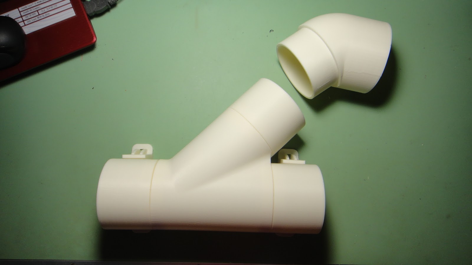
This photo is of all of the 3D printed parts that will be used in the exhaust system of the spray booth. The large part at the center of the photo is a "Y" connector and slid into it are extensions for the flexible hose that will connect to the two exhaust fans. All of the parts have an outer diameter of three inches. Just the "Y" part without the smaller extension took 8 1/2 hours to print. But it like all of the other parts simply cannot be bought. Cost to make the parts were around $8.00.

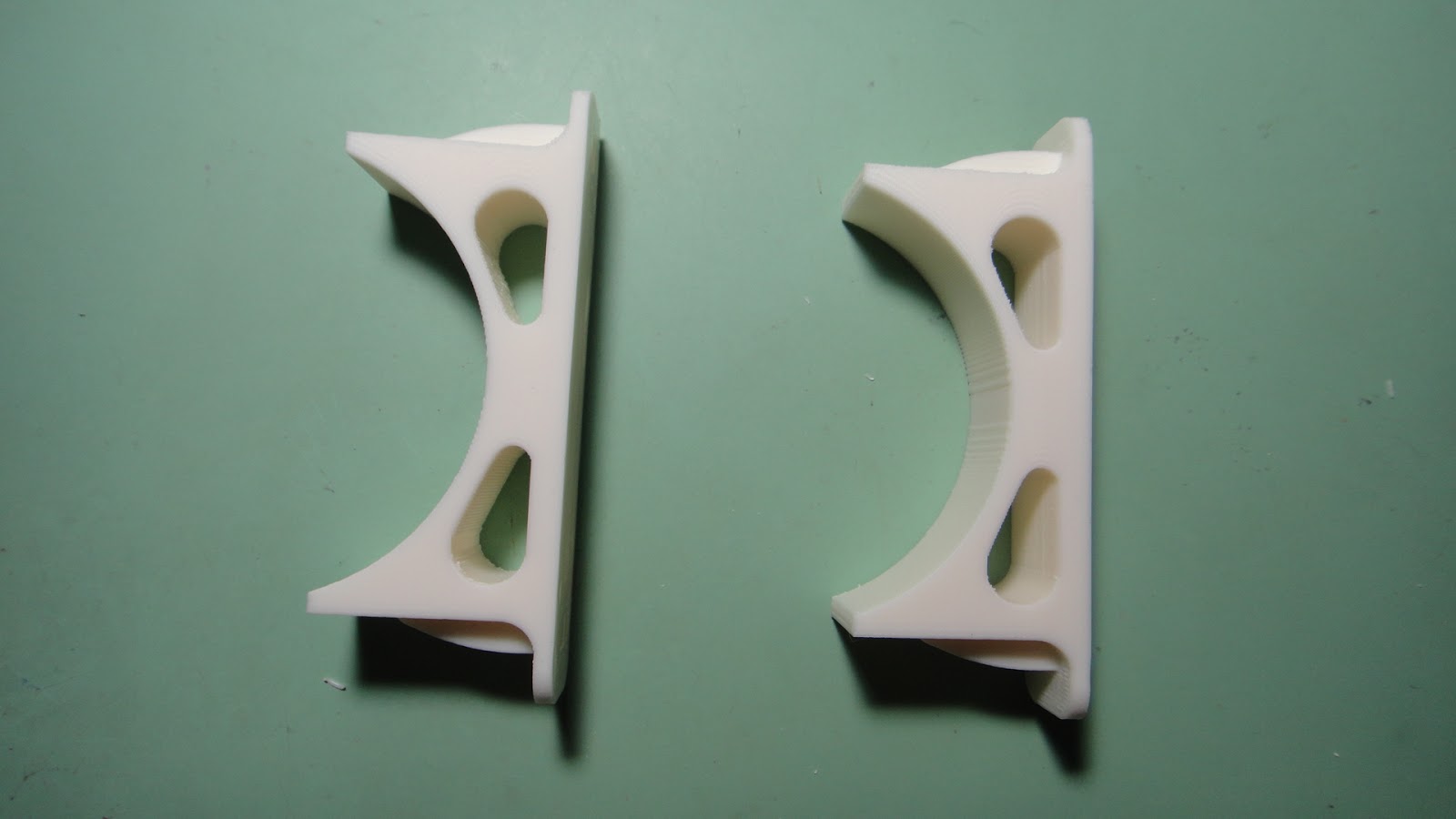
The top photo above is the same "Y" connector with the extensions along with the mounting parts that you see in the lower photo. The "Y" connector and it's parts will be tied together to the lower mounts using zip ties. The zip ties that will be fed through holes in the back of the spray booth and should stay in place rather nicely. Simple is always a good thing. So with that sorted out I started working on the construction of the spray booth itself.


The photos above are mountings of the framework for the spray booth that surround and hold the furnace filter in place. I stacked and glued two pieces of 1/2" plywood on two side of a 2 X 2. I needed two complete assemblies that were exactly 1" square. I didn't have any wood that I could cut down to that size so I used what I had on hand. Doing it this way was a bit more work but I still managed to get what I needed and the parts end up inside of the spray booth and will not be seen once the booth is completed so it really didn't matter how they looked as long as they did the job.

I then attached a three inch wide strip of 1/2" plywood to one side of these first assemblies. This strip of wood is the guide for the furnace filter so that it can easily be installed into the spray booth.


I next took the two small assemblies and attached them to the front filter face that was cut out of 1/2" plywood (top photo). The middle photo is another small assembly that was used in this portion of the build. It is simply two pieces of 1/2" plywood 2" wide and 25" long glued together. They are used in the final assembly to center the furnace filter vertically with the front filter face opening. The lower photo is the backside of the assembly with the furnace filter installed into the assembly.

Next after carefully checking my computer model dimensions of the assembly I positioned the filter frame assembly on to the base of the spray booth which again was made using 1/2" plywood. I clamped the assemblies together.....checked and rechecked that I had it all in the right place and then screwed the base to the filter frame assembly.

With the filter frame assembly nice and secure I mounted the sides and top of the spray booth. I made sure that the slot for the furnace filter matched up with the top plywood part slot. I again clamped everything in place and then screwed it all together using fine thread #6 -1 1/4" drywall screws. At this point things were coming together nicely as you can see from the photo above.

I then got to work on the turn table that will be used in the booth. As with the rest of the assembly I used 1/2" plywood to cut out a nice 18" diameter circle. I had marked center lines on the square part before cutting it to get my holes lined up for assembly of the bearing plate that will make the turn table work.

Here is the bearing plate along with the mounting holes set up for it. The bearing plate will be screwed to the circular 1/2" wooden piece and then in turn it will then be screwed to the inside top surface of the base of the spray booth. The larger holes in the photo are there so that the turn table can be rotated to allow the lower screws to mount to the spray booth base.

I figured right with the size of the turn table as you can see in the photo above. The turn table is 18" in diameter and the inside of the spray booth is 20" x 29" in size. I thought this might be to large but from the looks of it..... it will be a nice sized area to spray parts in.

Back to completing the spray booth construction I assembled the mount for the upper exhaust fan. It was simpler to assemble the little shelf while the back of the spray booth was not mounted to the rest of the assembly.

I was really happy that I had more than enough clamps to get the last large piece of the spray booth held in place. There is no such thing in a workshop as to having to many clamps. Before I started clamping this last part in place I was not sure I had worked everything out correctly. Once I clamped it all down I breathed a sigh of relief as the fit-up was near perfection. Nice to see for sure.


With the back of the spray booth in place the fit looks great. The smaller box on the lower portion of the back is the mount where the electrical switch will be located for the booth. Again I put this little box together before mounting it to the main assembly. Made things a lot simpler.

Now with all of the wood construction completed I was able to get this shot of the two exhaust fans that will do the work of moving the air while I am using the spray booth.

The wiring as you can see will be fed into the lower switch box and then wiring will come out of the box and be used to plug into a wall socket. A nice clean installation.

This is how the entire exhaust system will look once I get it all wired and hooked up to exhaust hoses. But that will come in the next installment of this project. I more than likely will paint the spray booth rather than varnish it as shown in the photo above. This will make is simpler down the line if I should ever want to spruce up the spray booth after a couple of years of use. So that's it for today. I'll keep plugging along on this project and I should have it wrapped up in the next posting. Have a good one.


