Friday, February 23, 2018

A New 3D Printer And New Enclosure Project

On Christmas day this past year I placed an order for a new Creality CR-10 S4 3D printer.  I was amazingly surprised to have it in my hands three days later.  Along with the new printer the next day I ordered an upgrade to the heating element for the printer as I wanted to 3D print using ABS filament. I found after research that the stock heating element had a hard time coming up to the 110C temperature so that was my reasoning to update it right off the bat. The new Keenovo heating element I ordered the day after Christmas and it took seven weeks to get it into my hands thanks to Customs holding on to it in New York most of that time.  But no matter what things have been looking up since this long wait and I now am able to show you the end results.


Here is my new 3D printer in the new enclosure that I completed shortly after the new heating element was installed a few days ago.  The enclosure I lucked out with as far as materials for it was concerned as I had a pile of 3/4 inch square aluminum tubing stored away in my shop that was perfect for the job.  I 3D printed all the connecting components on my original Makerbot Replicator and then covered the outside with 10 mil plastic. Nice and heavy and very clear compared with other plastics I had looked at.


Here is a good shot of the interior of the enclosure with the new printer.  Lots of room and I was lucky to have just enough space on my old drafting table to hold it all without it looking out of place. 


The large black box in the image above is the control box for the Creality CR-10 S4 printer.  Next to it is a smaller controller for the Keenovo heating element (reading 106.1). 


Here's a closer look at the Keenovo heating element control box.  Very simple and very fast heat up with this new unit.  A vast improvement over the original heating element that comes with the Creality printer. My Makerbot 3D printer takes around 8 minutes to come up to temperature to print ABS filament.  With this new heater it only takes around two minutes. 


Here's a good look at my design for the enclosure for the 3D printer that I put together using Fusion 360 CAD software.  The enclosure is 27.5 inches wide, 27" tall, and 38" deep.  I needed this much space to easily hold the 3D printer and not have it have any issues with movement of the build platform while printing parts. 


The two images above show off one of the hinge assemblies that I use for the doors on the enclosure. These were 3D printed and then mounted into the aluminum tubing using 1/4-20 hardware.  


Here is a good selection of all the different types of 3D printed connectors that needed to be made for the enclosure.  This took some time but being as I was waiting for weeks for the new heating element it was the perfect time to make these components and get the enclosure in shape before it arrived.


Here is the enclosure being put together in the workshop.  Being on the work table it gives you a good idea of how large this assembly is.  Luckily it is very light weight and at this point can easily be taken apart to move it into my workroom where I actually make 3D printed parts.


Here's another look at the real hinges that are used in the enclosure.  I was really pleased with the fit and finish of my design.  The doors work perfectly. 


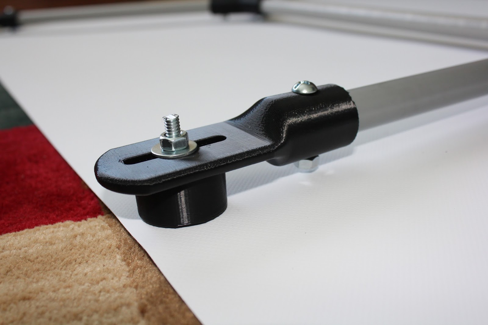
At the base of the doors is this 3D printed assembly with a couple of 1/4-20 bolts and nuts attached to it.  I needed a good metal target on this part being as both front doors have small magnets mounted in the bottom corners of the 3D printed connectors that make up the framework of each door.  These magnets are press fit into the frame and when the doors are closed the magnets click into place on top of the heads of the small bolts in this assembly keeping the doors securely closed.  Simple and effective. 

Once I had completed assembly of the enclosure and got the new 3D printer up and running I needed to figure out how to route all of the wiring for the 3D printer into the enclosure without causing any issues along the way.  On the left side of the enclosure rather than completely seal up the back portion of that side with clear plastic as I had done with all the other sides and doors on the enclosure I left the bottom portion of the plastic unsecured.  I did not tape it down as I had done on all the other panels.  This allowed me to snake all of the wiring into the enclosure through a small gap at the base of the panel.  I also made another small gap that runs vertically near the center of the enclosure on the left side.  This allowed me to route additional wiring and the plastic filament for the printer's extruder into the enclosure. I wanted to keep these openings as small as possible to retain the heat that is needed to make good ABS plastic parts.  


One feature that I always wanted on my 3D printer that I did not have on my Makerbot was a WiFi video camera.  So I installed one into the new enclosure.  I picked up this nice little security camera at Walmart and worked out the mount for the camera and located it on the upper front right corner of the enclosure.  I can watch any 3D part being made on either my iPad or my phone so I don't have to be sitting in the actual room where the printer is at to keep a eye on it's progress.  A good safety feature as well. 

I put a thermometer into the enclosure while printing one of the first test parts on the new printer and it read 96 degrees!  Plenty warm enough for the printer and a good confirmation that my design for the enclosure is sound. Now all I have to do is make final adjustments to tweak the new printer and I will be making bigger and better parts than ever before.  I have already made plans for some rather large projects that will be coming up in the near future and should be a lot of fun to work on.  I'll keep you up to date with this new addition to the workshop. Another good day in the shop!

Friday, February 16, 2018

Space Patrol Pistol Project Part 2

This week's post brings with it some very nice progress on my Space Patrol pistol project with all of the parts having been 3D printed.  (All 34 hours worth.) Or at least all of the parts that needed to be 3D printed along with the laser cut Plexiglass parts and various bits of hardware, decals, etc.


With the work that I completed earlier this morning small changes needed to be made to my design of the pistol.  In the photo above there is a small vent just above the power control panel on the left side of the model that needed to be changed.  Originally I had planned on a small row of columns to make up the inner portion of the vent.  This did not work out so well on my 3D printer being as this part was very small and it was hard to get the look that I was going for.  So it was modified to what you see in the image above.  Much easier to create and still a nice look for the pistol.


To create the body of the pistol I needed to split this portion of the design in half as it would have been near impossible to 3D print it in one piece.  This as you will see actually added a little more work to the project and will still look the same once I have it completed.  I really like the little extruded spaceship image on the right side of the body along with the control panel for the power display that will be on the left side of the pistol.


The top photo shows the circular indent in the body of the pistol where the vent assembly will be mounted.  Also in that photo as well as the lower image you can see the mounting holes on each piece of the body that will hold the body cap in place to the body once final assembly takes place. These parts were sanded smooth at this point to prep them for assembly to each other.


To align both halves of the body to each other I designed the parts to be able to hold a short section of threaded rod in them as alignment pins.  The only reason I used threaded rod was that it was spare parts that I had in storage in the shop and were handy at the time.  The rods are 1/4-20 threaded rod cut to 3/4 inch in length and epoxied into place.  Aluminum rod would have worked too but this served the purpose just as well. 


Once I had the pins installed on one half of the pistol body I then laid a layer of micro-balloons and epoxy putty mixture on the joint where the two halves would meet and rubber banded the two halve together to hold everything in place to create a good joint with proper alignment.  


Once the epoxy had cured overnight on the body I was able to sand the joint smooth to start getting the body ready for paint.   Pictured above is the body along with the body cap.  The cap slides into the large opening of the body and is held in place with two 1/4-20 button head bolts and nuts.  The cap holds all of the components that make up the front of the pistol that you will see further along in this post.


The photo above shows most of the components that make up the front of the pistol.  Starting at the left side is the mounting ball.  Inside of this spherical shape is a permanently mounted 1/4" nut that is needed to hold the 1/4" threaded rod shown at the bottom of the photo that holds everything together.  The next three white pieces make up the stem of the pistol and placed between these pieces are the color Plexiglass disks. 


The thread rod runs through the entire assembly and is mounted to the body cap when the remaining pistol components are added to this part of the assembly.


Here is the final components that will be mounted to the stem assembly and the body cap as well as additional parts that will be added to the body of the pistol.  At the upper left is the dish and next to it is the body cone. On the bottom row is the vent shield and ring that will be mounted on to the body of the pistol.  The last part is the trigger for the pistol grip. 


Here are a couple of good shots of the pistol grip.  The larger pieces will be joined together and then painted gloss black.  Once this has been completed the textured inserts will be painted red and then also joined to the pistol grip as shown above. 


 With the Plexiglass disks in place on the stem of the pistol along with the dish you get a much better idea of how the design will look once it has been completed.  The pistol grip inserts into a slot on the bottom of the body of the pistol and will be Super Glued into place once the painting has been completed. This will also be the case for the trigger, vent enclosure, and power setting knob as shown in the first photo of this post. 


The seam on the spherical ball on the end of the pistol stem will be filled in, then smoothed and then painted gloss black.  Along with all of the other components that need to be prepped for paint I will have to track down the button head bolts that hold the body cap to the body and the project will be ready for final display.  I will also have to figure out a mount for this pistol similar to the one that I made for my first pistol named the Skrooch gun so that I can easily put it on display. (See December 7th, 2017 post)  As you can see I still have my work cut out for me over the next week or so.  Not difficult but as usual time consuming and still fun just the same. 

The finished pistol will be 13" long and 9" tall.  It's impressive already and I don't even have it painted yet.  (I'm impressed anyway.) I'll let you know when I get all the painting done and the little details added to this project. Then I can let the dust settle once again in the workshop and set the pistol up to display.  Stay tuned for further developments.

Saturday, February 10, 2018

A New Velomobile Poster To Brighten Up My Garage!

As most of you already know I am a big velomobile enthusiast and have built my own design that has been posted about here a lot over the past few years.  This morning I completed a project that has been on my mind for quite some time.  To give you a little background on the idea for this project I have to point you to the following site.


On this site is a link to a book that was put out a number of years ago.  The book is a documentary of a group of fifty-five velomobile drivers who crossed the United States in 28 days with their velomobiles.  From Portland Oregon to Washington DC.....over 3200 miles. On the site is the following image that has stuck in my head for all of this time and led me to the creation of the project that I completed today.


This image has stuck in my head for years and I always thought that it would make a great poster.  Sadly none was ever produced.  I could not even find out who had created the artwork and so the project never got off the ground until I decided to try and duplicate the image myself and make my own poster.  I wanted the poster to be large enough to hang in my garage. 


I measured the Indian motorcycle poster that I have in my workshop which is six feet wide and 30 inches tall.  This was the size I had in mind for this project. So the velomobile poster project was born.


In order to create the large poster I used the same company that had made my Indian motorcycle poster....Vistaprint.  That was the easy part.  But I knew that I could not use the original Roll Over America image as it simply was not large enough to get a perfectly clear image once the poster had been created.  Being a smaller format to blow it up bigger would create a blurry poster. So I needed to duplicate the poster from scratch.  You can see the start of my poster above along with the original image below it.  


Here is my final poster that I created using the original as a guide.  It is not a perfect copy by any means but it is a good knock-off so it works for me.  The lettering was the easy part of creating my copy but making all of the velomobiles took me several long days to get the colors and lighting the way I wanted them.  Again the best I can say is that it's a pretty good knock-off.  Once I had my version of the poster completed I sent it off to Vistaprint to get it made.


The original frame for the Indian motorcycle poster had a rectangular frame similar to the one that I have pictured above.  The original computer files were lost some time back so I had to try and make the framework again from scratch in Fusion 360.  This would have worked out fine but I decided to change this a bit with this new poster.


Rather than make the square frame over again I came up with this new design that used fewer parts and ended up being lighter in the process. All of the components except the tubing for the new frame were then 3D printed for the assembly.


Here are the three main types of fittings that I 3D printed for the new frame.  Each took some time to 3D print as I suspected but they turned out better than I had hoped.  Nice clean prints and very strong for this project.


To get the tubing drilled correctly for the new framework I 3D printed a drill guide for the ends of the tubes.  The drill guide is flat on the bottom to keep the drill hole lined up perpendicular to the PVC tubing and create a perfectly centered hole. 


An additional drill guide is slid on to the opposite end of the tubing to keep it parallel with the table and easier to hold the setup while I was drilling the tubing. 


The hole in the drill guide makes alignment of the drill bit to make the hole very easy and as you can see it makes a perfectly centered hole exactly where I need it to mount all of the parts for the assembly. Each hole was exactly 3/4" from the end of the tubing on both ends  for all parts. 


After I had the assembly for the frame put together I laid it on top of the back side of the poster to check the alignment of the grommet holes with the mounting frame.  All of the mounts lined up perfectly and the framework slide together easily. 


A cylindrical spacer was 3D printed for all of the arms that keeps the framework separated from the poster.


On the upper mounts I attached metal tabs that would hold the small chains that were used to mount the poster framework to the wall.


To mount the poster to the wall all I needed to do was install three "I" bolts and add the small chains with hooks on both ends.  It brightens up my garage in a big way.  I thought the poster looked big in my house but once I had it mounted in the garage it looks much smaller.  Either way I think it looks great with my velomobile parked under it.  Also the framework to hang the poster is almost completely hidden behind the poster which gives it a nice clean look. Vistaprint did a great job of making the velomobile poster out of quality heavy vinyl so hats off to them once again as well.

Another good day in the workshop and another project I can scratch off my bucket list.