To christen the new Tinker's Workshop today I started construction of the CNC computer desk project. Over this next week I hope to get the desk put together so that I can fire up my CNC machine once again after a long absence.
Having just completed work on the rebuild of the work table for the shop was a must. I was putting it to good use today layout all the pieces of plywood that will be needed for the CNC computer desk.
Most of the parts for the desk were cut out using a hand held jig saw. This was definitely the tool of the day for cutting out the holes in the sides and back of the desk. I marked out the holes first using a good drafting compass and then drilled a quarter sized hole to slide the jig saw blade into. Then just stay in the lines and follow the circle to cut it out. Piece of cake!
I will clean up the holes further using a drum sander to make sure they are as perfectly round as I can make them. Already in this shot of the back of the desk, the holes look almost ready to go. The orange paint on the edge of the plywood is another thing that will have to be sanded off. Just happen to have been put on the panel before I bought it. Easy to take care of.
Here all the parts for the desk are laid out with corresponding drawings of each part either for more machining or just for identification when it comes time to put the desk together. I also will have to sand everything nice and smooth before assembly as it will be more difficult afterwards. Like I said earlier this big work table is worth the effort to put together just to make projects like this easier to work on. Much simpler than a smaller table or worse yet having to lay it out on the floor. Saves the knees and your sanity all in one step. More postings on the project will follow soon.
This project has been on my workbench/worktable for quite some time so I am happy to announce that my Makerbot Walking Machine has been completed today! I had seen something similar to what you will see here online some time back and thought " I can build that! And for less money too! ". This little walking machine was quite a puzzle to design and build. The key to the movement of the legs is a cam shaft that is built into the center of the machine. This was a real trick to get to design and work properly. The next problem was just assembling all of the parts around that cam shaft. A challenge that turned out to be worth the effort.
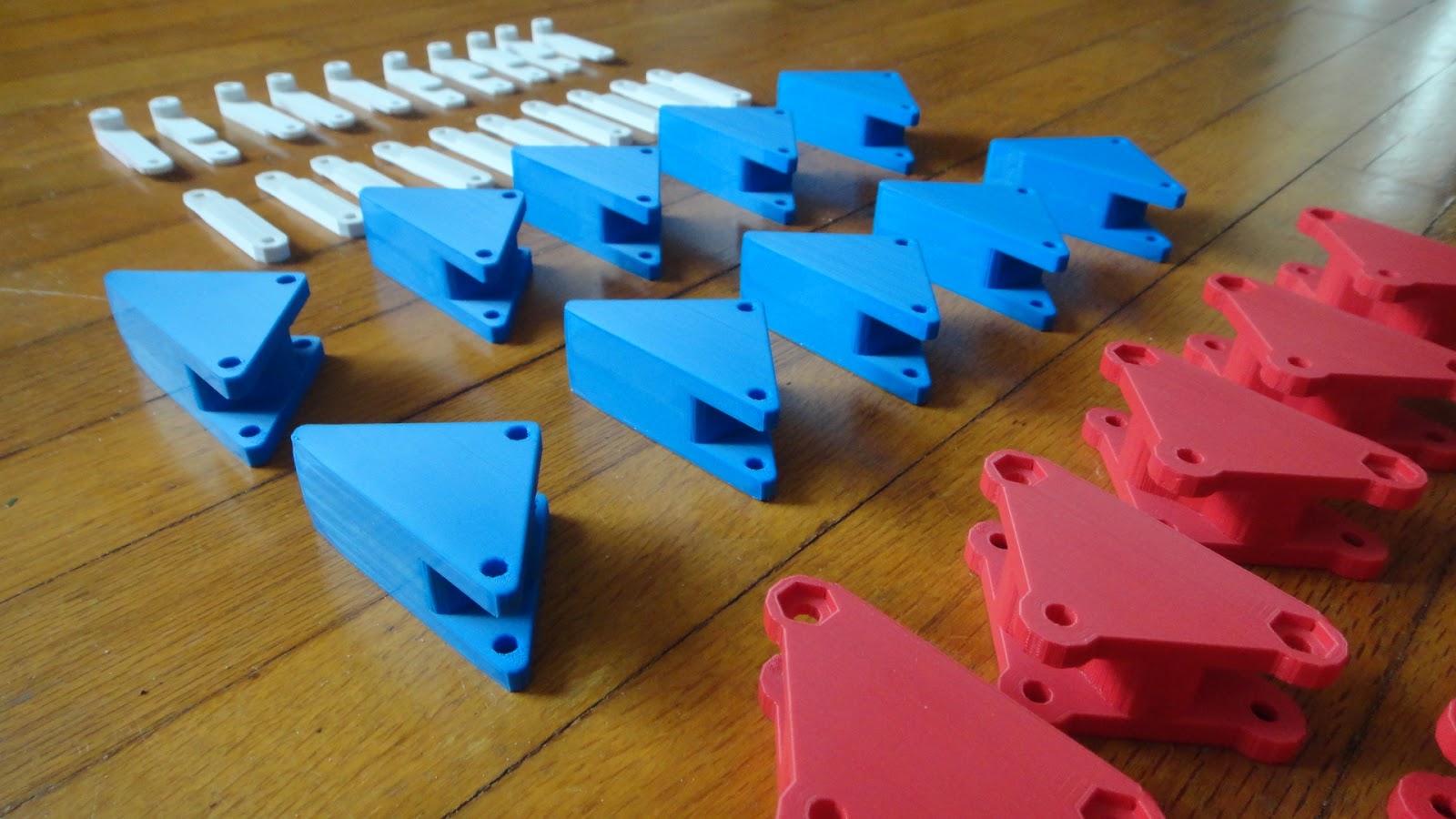
This is a good shot of the parts that I printed on my Makerbot Replicator 3D printer. The red parts took two hours each to print. This was before I upgraded the software and the time then could be cut it half. (See an earlier post on the upgrade).
This is the first camshaft that I designed. It looks good but it was difficult for the shaft to maintain the correct orientation for each cam. This was scrapped and a new design came out of what I had learned from this first effort.
Parts, parts, and more parts.
Three threaded rods were used to hold the assembly together. That and a lot of nuts to position all of the Makerbot printed parts and the camshaft.
Here the threaded rods were mounted to the first of six spacer plates. I used nyloc nuts which held everything secure. The only problem was that running these nuts down the entire length of the threaded rods was time consuming to say the least.
This shot shows some of the major parts that went into each of the ten legs on the walker. The Makerbot Replicator printer really did a nice job of printing the parts for the machine.
Assembly was started in ernest in this photo. Looks more like a big pile of plastic with no organization at all. As I said earlier this was a real puzzle to design and put together. I figure the total time just to assemble the machine was close to six hours. As there are over 280 parts in the machine if you count every single part including nuts, bolts and washers.
As the saying goes... A clean desk is a sign of a sick mind. In this case I am not so sure.
Here the first set of legs are assembled on to the spacer plates. I was glad I choose to print the parts in various colors. Makes it stand out a bit more than just say printed all in black or white.
Here the Makerbot Walking Machine is assembled.... for the first time. After I found out that the original camshaft that I had designed was not working properly I had to tear the machine completely apart to rebuild it with a better camshaft. Also after the second build of the machine I realized that the blue feet were mounted backward and the machine would not walk properly. Once these things had been corrected progress was the order of the day.
This was the key to a better camshaft. The problem that I had with the first design was that the camshaft kept losing it's orientation from one set of legs to the next. Each leg has a 120 degree difference in orientation and if this is lost it simply will not walk. So I designed a simple splined shaft that held the correct orientation for each leg. The machine was reassembled with the new camshaft and all nuts were mounted using lock-tite so nothing would loosen as the machine was played with.
This project has been sitting in boxes over the past four or five months due to my moving to a new home and other things that have gone on in my life so I am really happy to say this one is completed.
The completed machine is 8.25 inches wide, 12 inches long and stands 5.5 inches tall. Not sure about the weight. I suspect that it is less than a half pound.
Check out the little video that I put together of the machine running on my kitchen table. Due to the fact that the feet of the machine are hard plastic it does not have any grip on a hard table. This is why I added a knob on the side of the machine to make the legs walk. If I sit the machine done on a low nap rug and move it the machine will walk without the knob. As I said it has been an interesting project to design and build. Something else that will go nicely with all the other projects that have the Tinker's Workshop name on it. Enjoy the video.
As usual click the Youtube button below the video to get a bigger view.
The final piece of the new Tinker's Workshop puzzle was completed today with the building of a big work table for big projects. The original table in the workshop was 4 x 6 feet and with the new shop being twice as large as the old shop this table just would not do. I decided to enlarge the table size to a full 4 x 8 foot by 35 inches tall. Even with this larger table it is not a problem in the new shop to get around the big table to work on what I want to when the time calls for it. The height of the table is perfect for standing next to or using my shop stool to sit and work on something without having to bend over to reach something. Do that often enough and working on a project can literally be a pain.
The framework for the table is made up of standard 2 x 4 lumber. The middle pieces are cut three inches short so that four 2 x 4 foot panels could be mounted to them securely using #10 1 1/2 inch wood screws. I could have used just one big sheet of 4 x 8 foot 3/4 inch plywood but I had the smaller panels on hand so I thought I might as well use them on this simple work table.
All four legs of the table are securely bolted to the table top using 1/2 inch nuts, bolts, and washers. As all the legs are drilled exactly the same putting the table together is easy as any leg will fit in any corner of the table top. The table top frame is screwed together using #10 3" long wood screws. Once the top is mounted to the framework it is very solid and strong enough to easily stand on top of.
In this shot you can see the amount of space that I will have around the table. To the left of the table will be the big double door for the shop so large items can be moved into or out of the shop. The table is light enough to slide over to allow the double doors to be opened easily when the need calls for it. This will not be a daily thing so it should not pose a problem to leave the table where it is on a semi-permanent basis.
This is a good shot of the far end of the new Tinker's Workshop. With the table being completed it is a nice addition to the shop and should serve me well in the coming months/years that I plan on using it. Also today the doors for the shop had been delivered and hopefully I will get these installed in the coming weeks when I can get my good friend Garry to give me a hand with the installation of them. The shop will be warmer with the doors on as the heat will now stay in the shop instead of moving to the rest of the basement. I am still thinking about possibly doing something with the floor but for now this will do nicely.
Next on the agenda for the new shop will be the building of the much needed computer desk for the CNC machine. (See an earlier post to check out the design). I have the wood for the desk ready for cutting so getting a new project started in the Tinker's Workshop will be the order of the day and another reason to smile.
This past week I have been busy firing up my Makerbot Replicator 3D printer once again after a long absence. I had upgraded my software on the Replicator only to find that changes had been made that I was not aware of. Good changes that managed to get me messed up trying to print simple parts. The new upgrade in the firmware now made my Replicator run faster but erratically at the same time. Kind of a good bad thing if you know what I mean. This actually turned out to be a very good thing as I had not printed anything on the Replicator in a couple of months due to my moving and getting the new Tinker's Workshop set up. With doing the upgrade I started doing research once again online to catch up to the rest of the Makerbot world. This is what I had found.
Last October a couple of gentleman had developed a new version of the ReplicatorG software. (This is what is used to tell the Makerbot Replicator or any other 3D printer how to print parts.) They call their version ReplicatorG - Sailfish. I did my homework on this software and managed to get my Replicator upgraded again with this newly developed version ( # 039 to be exact). I was pleasantly surprised at how easy it was to set up on the Replicator with the supplied instructions that I had found online. It only took me around 20 minutes to upgrade everything and get the Replicator running beautifully.
The Makerbot Replicator out of the box prints at around 40mm per second. With the new upgrade of ReplicatorG - Sailfish my machine is now running at an astounding rate of 200mm per second! Five times faster than before. With this amazing speed also comes smoother printing with less vibration and with this the noise level has been reduced by what seems to be at least half. The prints are finer and now my Replicator is running like it is a totally different machine.
To give you an example of printing speed, I had to reprint a couple of parts that I had managed to break today. (My fault not the machines.) The original parts each took two hours to print. When I reprinted the parts after the upgrade I was able to print both parts now in two hours. I had cut my print time in half! For more information about ReplicatorG - Sailfish go to the following link.
At this link you will find the information that you will need to upgrade your Makerbot too! You won't regret it as it is well worth the little effort that it will take to make you machine get up and fly when it is printing. Here also is the link you will need to download ReplicatorG - Sailfish to your computer.
Just click the "Download" button to get the version that will work with your computer and 3D printer. If I had known about this software when it came out months ago I would have downloaded it immediately and saved myself a lot of time printing parts. Don't wait any longer than you have to. Pure and simple.... get this software upgrade as soon as possible. You'll be glad you did.
While setting up the new Tinker's Workshop I find that I now need a place to put the computer monitor and keyboard that I use to run my CNC machine. In the old shop I simply placed these pieces on my large work table that sat next to the CNC machine. With the new workshop this is not possible as the work table is now on the other end of the room and makes the idea useless. So I need to make a new desk to hold the computer monitor and keyboard.
I have been working on the new design for the desk over the past week or so using my CAD software and have come up with something that I think will fill my needs.
This is the new computer monitor desk that I will be putting together. I found a design online that was similar to what you see here but was more elaborate that what I wanted. I used some of the ideas I found in that design to make my own so here it is.
The desk top surface is 36 inches from the floor with an area that is 29 x 18 inches in size. This will give me a good space for the keyboard along with room if I want to write something down. I wanted the desk height to be so that I could use my shop stool and sit at the desk comfortably and not have to stand while using it. The drawer makes a nice place to store paper and pencils if I need them along with anything else that is called for while running the CNC machine. The design evolved from over five or six different designs that I worked on over the past week or so. I wanted the holes in the sides and back of the desk just to give it a nice touch and get away from having the desk looking like a podium. The casters on the bottom of the desk will help if I ever should have to move the desk in the shop along with the CNC machine.
The vertical arm on the back of the desk will hold the monitor in place easily. The addition of the two vertical 2 x 2's on this arm will stiffen everything up and make it nice and solid. The arm will be bolted to the back of the desk using 1/4 inch bolts.
On the vertical arm will be another pivot arm that I found on Ebay for a good price and will allow the monitor to be pivoted and moved from side to side should the need arise.
This pivot arm is mounted to the back of my 19" monitor that I removed the base off of. This was an easy task to accomplish as it was only a couple of covers and four screws to get the base removed. The pivot arm is made for this type of mounting and so almost any monitor can be used for this installation.
Here is a few good photos of the actual pivot arm that will be on the new desk. It only cost me around $15 for the arm on Ebay with free shipping. Works for me. I still have to crunch the numbers to figure out what kind of wood to use on the new desk. This will be used in my workshop so it does not have to be made out of oak or teak or something else that is more expensive than it needs to be. I want it to look good but not cost me an arm an a leg to put together. As I said earlier I had gotten some of the ideas for the desk from another site that I had found but their desk ended up costing them around $400 to make. A beautiful desk to say the least but I do not want to spend that kind of money for my design. Here's the site for the desk that I used for ideas for my design.
This will actually be the first project in the new Tinker's Workshop. I think it will be worth the effort as it will be another piece that will fit in well with the shop and help me get the CNC up and running again. So it will be a nice addition to the shop and another interesting project to post here. Stay tuned.