Thursday, February 20, 2014

An Inexpensive iPad Macro Lens and Adapter

A lot of times while working on projects here at the Tinker's Workshop I find bits and pieces of equipment that I've collected over the years and thought someday I could use this for something.  This is the case with today's project.  Years ago when I was still shooting photos using a film camera I had my own darkroom to develop my pictures.  As I said this was years ago and I no longer use film cameras as most people do now a days and so I stopped developing film and moved on.  I came across a lens for the enlarger that has been floating around my workshop for some time as it makes a nice eye piece to look at something really close up.  Similar to the eyepiece a jeweler would use to fix a broken watch.  So I kept the lens and it has severed me well over the years.  Putting two and two together I thought why not make an adapter for the lens so that I could use it with my iPad and then I could take photos of what I see. So that is the project for today.


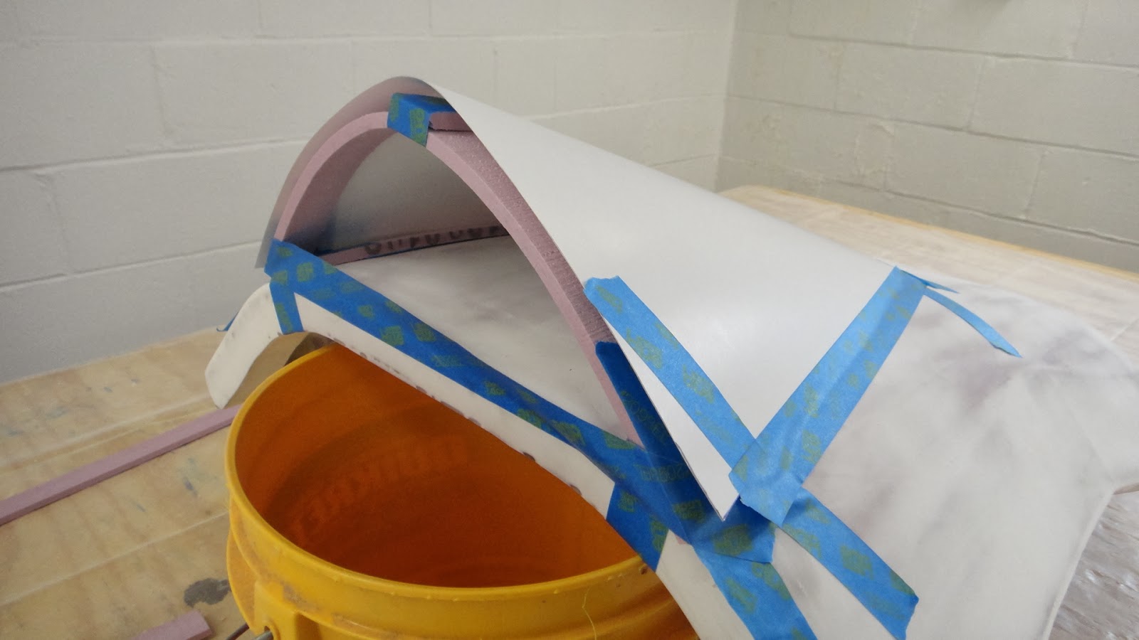
As I usually do I started with my computer design software to get the rough shape that I needed for the project.  This little box like object is the adapter that will fit on to the iPad and make the lens work with the camera.  The trick with this portion of the build was just to get the lens opening that you see here, the right size for the threads on the lens from the enlarger.  The opening is only around 1.5 inches in diameter and so I had to make two or three test parts to get the hole just the right size so the lens could be screwed into the opening or make it at least a friction fit. I would not want the lens to fall out when I wanted to use it.   Also the slot in the adapter needed to be the right size so that it would slide on to the iPad and also stay put.  I have a protective cover on my iPad to keep it from getting damaged and so I needed to allow for this extra thickness while making more test parts for this opening as well.


My 3D printer did it's usual wonderful thing and created this slick looking adapter for the little lens that you see here. 


After several test parts were made the lens and hole in the adapter were a perfect match. As you can see the lens and adapter fit well together and the set up looks good too.


The adapter is slide on to the upper corner of my iPad here in this photo.  You can see the protective outer case that I use on my iPad in this photo as well.  The lens at this point is aligned with the camera that is built into the iPad.  This alignment needed to be just right and so it too took several more test parts to get it made correctly.


This is what I see on the iPad when I am ready to take a photo.  I could have used an assistant with this photo as I need to hold the little Lego man in front of the lens, focus the camera and shoot it too. Thank goodness that I had the iPad on my tripod to at least hold that still for this shot. 


To give you a better idea of what a difference this little lens makes to take macro photos I shot this photo first without the lens on the iPad. This photo above is the closest and clearest photo I can take with just the standard lens.  Not good at all.  Fuzzy to say the least.


Now this is the same shot using the new lens and adapter that I just put together.  Quite a difference don't you think.  The photo does have it's draw backs as you can see simply because it now is black on the outside and circular in the center of the photo.


Here's and even better shot using the new lens.  I like the fact that it is so nice and clear and the detail is so good that you can even see my finger prints in the photo.


The final step in the process of getting the shot that I wanted was just a matter of doing a bit of cropping of the photo to remove the circular view and the black around the outside of the image. This is pretty cool considering I'm using an old discarded enlarger lens and less than a dollars worth of plastic from my 3D printer. A tinker's project for sure. Well worth the time and money to put together. Enjoy the photos. 

Tuesday, February 18, 2014

Refining The Velomobile Windshield Design

The last few days have brought more snow to the workshop along with some nice improvements with the velomobile windshield installation.  As I do not much care to even look at the additional snow doing anything in the workshop is always the better choice.  So with that in mind here is how this portion of the velomobile project has progressed.


In my last post this is as far as I had gotten with the windshield installation.  The black clips that you see here gave the right shape that I wanted for the windshield but just not the right look.  So I shifted gears and started planning a new course of action to get what I was really looking for.


What I did as shown in this photo was to first remove the two front clips as I found that they distorted the shape of the windshield just a bit when installed.  I then removed the windshield and covered the lower edge with painters tape, re-installed it back into place using the four remaining clips as guides to hold the shape that I wanted.  I then covered the clips on the outside again with more painters tape.


Here I laid out two pieces of fiber glass cloth that would make up the new mounting for the windshield.  This will make more sense once I proceed so that you will get a better idea of where I was going at this point. 


Here the windshield has been completely wrapped with several layers of 8 ounce fiberglass cloth. Already the assembly looks a lot better than before.  The blue tape allows the windshield to be removed after the fiberglass has cured over night.


The next morning I was able to remove the windshield with a little effort by sliding a Popsicle stick between the windshield and the painters tape.  Once I got that far I was able to break the seal between the fiberglass and the tape.  Then the windshield slide out easily.  Only took me two or three minutes.  I then unbolted the four remaining windshield clips as they were no longer needed. The next step was to remove all the remaining blue painters tape to clean up the assembly.  This was accomplished using a small grinding cone attachment that I had in my Dremel tool kit.  Made the task fast and easy to accomplish.


In this photo you can see that the first go around with painters tape worked out very nicely and I have a nice strong clean lip now to mount the windshield to.  The only problem that needed to be worked out was how to fill the voids now left by the four missing windshield clips.  I backed up the inside of the voids with styrofoam and more painters tape where I did not want epoxy resin to stick.  The lower portions of the opening needed to be filled completely to match up with the inside lines of the earlier mounted styrofoam. 


There is a closer look at what needed to be filled in on both sides of the new windshield mount.  


I laid down four more layers of eight ounce fiber glass cloth to fill the void and get a nice smooth flowing outer shape for the new mount.  


You can see in this photo where the rear windshield clips were and have now been filled in with new fiberglass.  The white that you see at the previous voids is a fiberglass resin and micro-balloon mixture that makes a great filler for just this purpose. This filler was put on to the exposed foam where the voids were and then the new fiber glass was laid over top to keep everything nice and even.  The inside of the lip also received additional coatings of micro-balloon mixture and another layer of fiber glass cloth to cover up any exposed surfaces to seal up this portion of the assembly completely.


After yet another night of letting the new fiber glass cure I needed to trim the upper edge of the new mount using my Dremel tool once again with a carbon fiber wheel.  I taped off around the upper portion of the mount again with my handy painters tape to create a guide line and started cutting.


Taking my time with the cutting wheel and then a small sanding wheel and then more hand sanding I ended up with the shape I was looking for. Now I was able to call the operation a success.


After installing the windshield once again without the black clips was just a matter of sliding the windshield under the newly created fiber glass lip.  This lip by the way now has seven layers of  fiber glass in it.  This has made is very strong and stiff.  Just what I was looking for.  


I took a look at the original mounting holes that were drilled into the windshield for the little black clips and compared the locations to the new fiber glass lip.  As I figured the holes were not in a good location.  So I traced out a new windshield without holes in it so it could be drilled at the same time the fiber glass lip was being drilled. 


 I was able to slide the new windshield into place quite easily as it was a perfect copy of the first one I had put together.  I then marked out where the new holes needed to be drilled and crossed my fingers just for luck and went for it.    It is hard to see but the idea worked perfectly.  So I (pardon the expression) managed to kill two birds with one stone once again. 


 Now that I have the holes drilled where I need them it will be an easy task to mount the windshield using 10-24 hardware.


I tracked down this type button hex head machine screw today so it will give the windshield a nice clean look. 


 Assembling the machine screws into the windshield and  fiber glass lip started with the one right at the very front.  This one needed to be first as the back of the windshield needed to be raised so that I could get my hand between the windshield and the dash to hold the nut and then tightening the screw.


I worked my way down the rest of the windshield from side to side  to get everything tightened up as you see it here.  Not hard to do  but just took a little while. The look now is just what I wanted when I started. 


 I still have to do the finishing work to blend the new fiber glass windshield lip into the body and the mounting already is a vast improvement over the black clips that I started with.  The clips were useful just the same as they helped keep the windshield located correctly onto the hood while I got the new mounting sorted out.  I can't wait to see the entire body of the velomobile smoothed out and painted..... ready for my first test ride.  Wishful thinking today as I look out my window at five foot of snow piled up next to my driveway......(sigh).  Stay warm and keep tinkering.


Thursday, February 13, 2014

A Nice Clean Windshield For The Velomobile

A couple of days ago my order of material for the windshield for the velomobile showed up at the shop. I had ordered some polycarbonate plastic online so I was happy that it had arrived in one piece.  What I needed was a strong flexible plastic that would be easy to bend into a nice shape for the windshield.  I figured 1/32 inch thickness would do the trick.  This is how this idea turned out.


In my last post on this portion of the project I showed you this computer image that I had put together to show you what I had in mind.  The plastic that arrived for the windshield was a piece 2' x 4" and was rolled up and put into a box that was 6" x 6" x 36" in size.  I knew if the plastic sheet could be rolled up that small the windshield would be a snap to bend into the shallow curve that you see here.


In the lower right corner of the plastic sheet I laid my card stock template of the new windshield.  As you can see I have more than enough plastic to make several windshields.  This I plan on doing just so I have a few spares on hand should I need to replace the original windshield.  The 2 x 4 foot sheet cost just under $15 including shipping.  So I figure that I can get five windshield made from this material and it will only be $3.00 each.  Pretty cheap windshields.


After I had traced out the new windshield I cut it using a standard pair of scissors.  It took a little effort but was an easy task over all. I then placed the windshield in place on to the front hood.  It looks great here and the shape and size looked to be right on the mark for this portion of the velomobile project.  The next step was to figure out how to attach the new windshield to the hood without a lot of hassle.  I knew that I needed some kind of mount that would be easy to assemble to the hood yet could be removed if every there was a need.  


I started with this simple little triangular shaped piece that I made on my 3D printer.  It was a spark of an idea at least.    


After a half dozen modifications I came up with this clip that I thought would do the trick of mounting the windshield.  I figured that I only needed six clips to hold everything in place. Three on each side of the windshield. I made three clips mirror images of the opposite side on the velomobile so that they would look right once they were mounted.  Each clip is only 1.25 inches wide and about 2 inches long. The hole on the right holds another 10-24 bolt which will mount all of the clips directly to the hood of the velomobile. 


The windshields outer edge slides into a slot in each clip and is held in place using a 10-24 bolt.  A 10-24 nut will hold the windshield securely in place in a receiving cavity in each clip.  


After measuring the placement of the windshield I placed the mounts on the the windshield temporarily so that I could get mounting holes marked for the clips.  Here the first clip has been mounted to the hood with the second clip already marked out for drilling.   The outer perimeter of the clip was marked on to the hood so that I could keep alignment of all the clips where they needed to be for the installation. 


In these last four photos you can see how well the assembly turned out.  As I suspected the windshield has risen off of the surface of the hood because of the mounting clips.  Along the sides of the windshield this gap is only around a quarter of an inch.  At the very front of the windshield the gap has risen to one inch.  Not an alarming discovery.  


So the next step in the process will be to fill these voids once again with foam and fiber glass.  In this photos you can see the general shape that will be feathered into the hood and around the windshield assembly.  


The large strips you see here will first be hot glued to the hood to keep them in place for the next step.  I will then add smaller strips of foam between the windshield clips.  I want to have the foam just bump up against the outer edges of the windshield.  At the front of the windshield I will have to build the foam up to an inch thick and taper it off to the outer perimeter of the large strips. I'll remove the windshield and sand the foam into shape.  I will have to recheck the fit again with the windshield in place once this is done. 


You can see the gap at the front of the windshield here in this photo.  I always assumed that I would need to do more body work to get a windshield mounted on the hood.  But I have lots of time before I will be able to get at the body work again as winter is still here in the Midwest in a big way. So the nice warm workshop will make this part of the project a real pleasure to do. Once I get all of the fiber glassing done I will remount the windshield again to show you how it all turned out.  I think it will be a good look.  Also with the windshield already mounted I found it to be very sturdy.  The slight bend in the polycarbonate windshield is not so severe that it puts a strain on the mounting clips but rather gives it a nice stiffness.  A good thing to have. Nice to see another portion of the project coming together as planned.

Wednesday, February 5, 2014

A Possible Windshield For The Velomobile

These past couple of weeks have kept most people including myself stuck indoors with a major case of cabin fever due to the winter we have been having.  Way to much snow and cold to last several winters has been the norm and so little progress has been made on the velomobile project. Even with the insulating that I accomplished before winter set in the garage is still way to cold to bring it up to a temperature that I can do any fiber glassing.  So my attention has moved to other aspects of the project.  Namely the idea or at least a possible idea for a windshield for the velomobile.


This is what I have in mind if I can get all of the pieces of the puzzle figured out.   The little windshield will be a nice touch to finish off the design of the velomobile and get it ready for use some time this year. 


I started laying out just a rough idea for the windshield using foam strips that were laying around in the shop and some masking tape.


The windshield only needs to be around three inches tall. After some tweaking I found the shape I was looking for with this simple process.


I then took some measurements from the foam strips and cut a piece of card stock for the windshield template.  As you can see from the photo the shape was good in the front and sides but the back was anything but good.  Way to short but it was far cheaper to see the problem than wasting a piece of possibly expensive windshield plastic.  


I cut a new template and fitted it into place on the foam framework and front hood of the velomobile.  This looks to be much better than the first attempt. 


The real windshield would not have this foam framework as it would not be needed and would ruin the overall look of the part in the first place.  


The windshield template looks good in this shot and closely matches the overall look of the computer image from the first photo in this post.  Next I'll have to find the right material for the windshield and work on the mount for the part.  I'll also have to do some searching online for the plastic I will need as I know that it will have to be pretty thin in order to get the shape that I want for this portion of the project.  If not that then I will possibly have to figure out how to vacuum form the windshield. Something I've been wanting to try for a long time anyway.  So I have my work cut out for me while I'm trying to stay warm like everyone else.  I'll let you know how it all turns out when I get the process refined a bit further.