
The winter continues to drag on here at the Tinker's Workshop and so to work in the shop or my computer room on my latest project has been a far better thing to think about than shoveling snow or bracing for another round of sub-zero temperatures that everyone around the country has been putting up with.
My latest project that I have been designing and refining on my computer has been the reworking of an idea that I came across online some time back. It is a working air powered motor similar to the one in the video shown above. I like the design but want to rebuild it using parts made on my 3D printer. I also want to scale the engine down to 1/4 or maybe 1/3 scale.

My new engine design is much smaller in size than the one in the video. The piston in the video is 5" square and in my version it is only 1.25" and is cylindrical as it should be. I also believe that my design is much more air tight so it will be a bit more efficeint while it is running. The flywheel in the wooden version is 15" in diameter as where mine is only 3.75". A much smaller package all the way around. Being also that almost all of the components of my version of this engine are plastic it will take much less air to make it move. But before I go into this further let's get to the testing part of this design and the reason for this post.

Here are all of the parts that I had to make just for testing out the fit and function of my planned 3D printed air engine. There are test holes for the 6-32 machine screws that will hold all the parts together first. (Square part with three holes in it on the left hand side of the picture). Next came a test part to make the capture cavity for the 6-32 nuts (next part right of the first part). The little square part with an circular indent and the rectangular part with two holes in it are for the shafts for the piston, flywheel, crankshaft, valve slider parts in the assembly. On the far right is a circular part and just below it is the actual piston for the assembly. The circular part is a test part for the piston cylinder that needs to be made. Lastly the six parts on the upper portion of the photo are test parts for the valve slider mechanism in the engine.
As you can see there is a lot of test parts here but in the long run it is much faster and cheaper to tweak these test parts than to make major parts for an assembly such as this only to find out it does not fit correctly. A test part can take only a few minutes to make and save you hours of work by not having to reprint major parts that are bad from the start.

This little engine when it is completed will only be 3.75" wide, 9.3" long by 4.125" tall. A very compact engine compared to the wooden version. Once I have the engine up and running only using air power (and very little air at that) I want to play around with using a compressed air bottle to make it run.
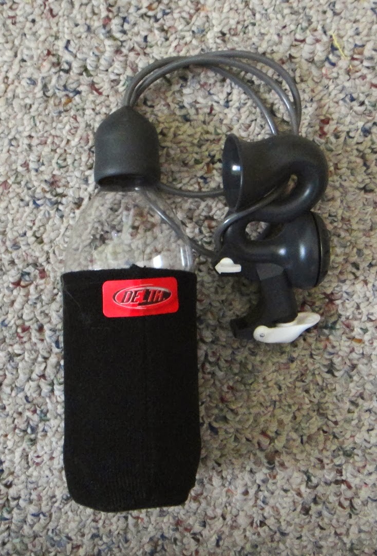
In my Velomobile project I already have an air horn for the vehicle that uses a compressed air bottle that looks like a one liter pop bottle. This little air horn comes from a company named Air Zound. I thought the same idea would work for this little engine to make it run. But first things first I have to just get the little engine to run at all. So it will be another interesting project to play around with until the weather warms up enough for me to actually get back to the garage to continue fiber glassing work on the velomobile project. I'll keep you up to date as I get farther along with this project. Stay warm and keep on tinkering.
My new engine design is much smaller in size than the one in the video. The piston in the video is 5" square and in my version it is only 1.25" and is cylindrical as it should be. I also believe that my design is much more air tight so it will be a bit more efficeint while it is running. The flywheel in the wooden version is 15" in diameter as where mine is only 3.75". A much smaller package all the way around. Being also that almost all of the components of my version of this engine are plastic it will take much less air to make it move. But before I go into this further let's get to the testing part of this design and the reason for this post.
Here are all of the parts that I had to make just for testing out the fit and function of my planned 3D printed air engine. There are test holes for the 6-32 machine screws that will hold all the parts together first. (Square part with three holes in it on the left hand side of the picture). Next came a test part to make the capture cavity for the 6-32 nuts (next part right of the first part). The little square part with an circular indent and the rectangular part with two holes in it are for the shafts for the piston, flywheel, crankshaft, valve slider parts in the assembly. On the far right is a circular part and just below it is the actual piston for the assembly. The circular part is a test part for the piston cylinder that needs to be made. Lastly the six parts on the upper portion of the photo are test parts for the valve slider mechanism in the engine.
As you can see there is a lot of test parts here but in the long run it is much faster and cheaper to tweak these test parts than to make major parts for an assembly such as this only to find out it does not fit correctly. A test part can take only a few minutes to make and save you hours of work by not having to reprint major parts that are bad from the start.
This little engine when it is completed will only be 3.75" wide, 9.3" long by 4.125" tall. A very compact engine compared to the wooden version. Once I have the engine up and running only using air power (and very little air at that) I want to play around with using a compressed air bottle to make it run.
In my Velomobile project I already have an air horn for the vehicle that uses a compressed air bottle that looks like a one liter pop bottle. This little air horn comes from a company named Air Zound. I thought the same idea would work for this little engine to make it run. But first things first I have to just get the little engine to run at all. So it will be another interesting project to play around with until the weather warms up enough for me to actually get back to the garage to continue fiber glassing work on the velomobile project. I'll keep you up to date as I get farther along with this project. Stay warm and keep on tinkering.
it is fascinating to me to see your projects develop on this blog. I have an antique steam engine toy that my wife's dad gave me years ago. It's far from being in good condition, but it does build up a head of steam and will spin the flywheel round and round. Steam and air motors are great bits of mechanicals and especially easy to understand.
ReplyDeleteI also have an AirZound2 horn in my velomobile, but I overpressured the thin-wall bottle too many times and it eventually blew its top. It also blew the visor on my cockpit cover open in the process. There's quite a bit of volume inside a small bottle pumped to about 100 psi. My answer was a 2-liter soft drink bottle with fiberglass overlay and an epoxy-steel product to keep the lid in place. The lid is a disk cut from 3/32" aluminum threaded for the hose fitting. I started at 80 psi for testing purposes and eventually reached and currently use 140 psi on a daily basis.
If you decide to go the custom route, you can find a parts list for more stuff than you might require at the bentrider online forum:
http://www.bentrideronline.com/messageboard/showthread.php?t=37196
McMaster Carr has great stuff, but it's always a challenge to me to know if something is the correct choice from all the available parts.