Wednesday, December 28, 2011

Rediscovered Projects From The Past

  During my yearly Christmas routine of putting up and taking down ornaments, trees, and various decorations I came across a folder with a lot of old photographs in it.  What made this find even worth looking at was the fact that the photos were of projects that I had worked on decades ago.  I thought the photos were long gone and forgotten.  So to show off some very early designs long before the Tinker's workshop even was a fleeting thought I present them to you here now. 


  The four photos here are of the airplane that I built from 1982 to 1984.  A long two years in a workshop of a friend of mine that I just recently have been in contact again with.  The plane is a Mitchel U-2 and was a real project to say the least.  It had a 35 foot wingspan and was of wood and cloth construction.  With the wings folded up it was still eighteen feet across. The engine was a converted Zenoah snowmobile engine. Complete with instruments and electric start.  A lot of people had asked me if the plane was a kit.  It was a kit only in the littlest sense.  If you can call a pile of wood and a set of blueprints a kit than I guess that's what it was.  The only thing that I did not build on the plane was the engine, wheels, instruments, and bubble canopy.  Everything else was built by hand with little or no support from the company that produced it.  Was a pain at times but also one of the best projects that I ever took on.  I learned a lot about airplanes and how to build them. 
  I never flew the plane.  I just did the ground testing on the plane and then donated it to an aircraft school in southern Iowa.  A lot of people are surprised that I never flew it.  I simply got burned out on the project before I got that far.  That and the costs to just keep it were getting higher each month it just sat in an open hangar at an airport 30 miles away from home.
  I read some place about guys who build airplanes and the statistics about the subject.  It stated that if 100 guys each started building an airplane only 20 of them will ever complete it.  So just the fact that I accomplished that much in this project I felt good about.


  This project turned out very well and took a lot less time than the airplane.  I still have this beautiful cedar chest at home and have had more than just a few people want to buy it from me.  The chest is four feet long, two feet from front to  back, and around three feet high.  It is all solid cedar that I hauled all the way from a mountain in Tennessee to Iowa and then planed down to one inch thickness. It is heavy!  It takes two people to pick it up and move it. 
  This was built in 1985 and still looks as good as it does here. Under each wooden button is a wood screw.  Over 300 were put in.  A lot of drilling to say the least.


  These two photos are of my drafting table that I designed and built in 1993.  My son at the time was four years old and is a good indication as to how big the table is.  I still have it but now is collecting dust in a storage room in my home.  It is solid oak and can be completely dismantled so that it can be moved from one place to the next without a lot of hassle.  
  I used the table to do engineering drawings for my brother for a couple of years and then later to create British sports car pen and ink drawings for a business that I ran for seven years.  That was another very successful project that actually made real money too!


  This photo is of my king sized canopy waterbed that I designed and built in 1979.  It took an entire day to put the bed up or take it down.  So you had to figure out where you wanted it and then measured the room very carefully because you would not even want to think about moving it once it was in place. It stood seven feet tall and was made out of pine stained in oak.  The waterbed as I said was king size which measured out at six feet by seven feet just for the mattress. So with the framework it now measured closer to seven feet by eight feet.  It was a beautiful bed complete with a mirrored canopy but very big to be sure.  I had it for a lot of years and then moved on to something a lot less time consuming to move.
  
  All of these projects were a lot of fun to build and now that I have the Tinker's Workshop up and running it just gives me a lot more chance to work on even more and exciting projects.  So keep checking in and hopefully you'll be even more entertained and encouraged to work on some ideas that you have been putting off in your own workshop.

Monday, December 26, 2011

I've Brighten Hearts And Living Rooms With My Christmas Angel Light Display

  
  Now that Christmas has come and gone I'm able to get this post put together and show off another project that I had worked on for a couple of Christmas presents.  I didn't want this shown until my sisters each had gotten a Christmas angel light.  The angel image I created using Corel software and it was engraved into a 1/4 inch piece of acrylic plastic.  I then cut it out using my band saw and sanded the edges smooth.  Also the bottom edge of the acrylic was heated with a butane torch to clear the plastic of the foggy effect you get when you cut it or sand on it.  This allows the light to shine through the finished piece better. In the rest of this post you see how I put everything else together.


   I started this project with a very nice piece of poplar wood.  I selected this simply because it is a very easy work to work with and as you can see it has no knots in it.  I machined the three wooden parts using my CNC machine to allow placement of the light and the electronics to run it and engraved the word "Peace" on the top face of the outer cover.

  
Here you can see how I clamped the two bottom pieces together to  drill out the hole for the light switch using my drill press.  The pieces were  held on the drill press using a small vise. This made it a lot easier to hold the parts tight enough to make the perfectly straight clean hole.  Another smaller hole was added to allow the wire for the power cord to be feed into the base of the display.


 A small slot was cut out of the center top groove that is used to hold the acrylic angel.  This allows the light to shine through the clear plastic.


The two lower pieces of the base were glued together at this point and allowed to dry.  I realized after I had drilled the holes for the switch and wiring that I could have glued these parts together first and it would have been a lot easier.  Live and learn.


 Two small wooden pieces made from 1/4 inch plywood were drilled out to accept the small led light that was used in the display. 


The light, light mounts, power switch, and a small 12 volt transformer were then installed into the base of the display. I set up grooves on the outer edge of the large pocket to accept the wooden light mounts.  This made for quick and easy assembly of the electronic components. 


Once I was satisfied with how the electronics were going to fit into the base I removed all of it to go onto the next step in the assembly. The top lid was screwed on to the light base using wood screws that were recessed into holes on the bottom of the base unit.  This made for a very clean look when the base was completed.  The parts were left assembled and then sanded smooth on a drum sander on my drill press.  


 The wooden parts at this time were removed from one another and four coats of polyurethane varnish was applied to each piece.  Between each coat I sanded it very lightly to get a good clean smooth finish.


The electronics were then reinstalled into the base unit and tested.  At this point I could breathe a sigh of relief as I am just a day one rookie when it comes to electronics.  Even if I only had to solder a couple of wires together.  Like every other tinkerer I am learning new things every day in my workshop.  Just have to put a little effort into trying something new once in a while.  I think my efforts have paid off very nicely.  My sisters think so too!

Thursday, December 22, 2011

Thank You!

  As Christmas is close approaching and the New Year will be here soon I wish to say "Thank You" to all the visitors that have taken the time to check out my little blog site.  You have given me a lot of encouragement over the few months that the blog has been up to continue working, designing, and dreaming up new projects for the workshop.  May you all have a very Merry Christmas and a Happy New Year!

Monday, December 19, 2011

When I say "Action"...... Roll Camera!

  It's been another busy week here at The Tinker's Workshop with another fun project and trying to get ready for Christmas and all the hustle and bustle that it brings.  This week I've completed something for all the people that are into creating video for the fun of it like me.  
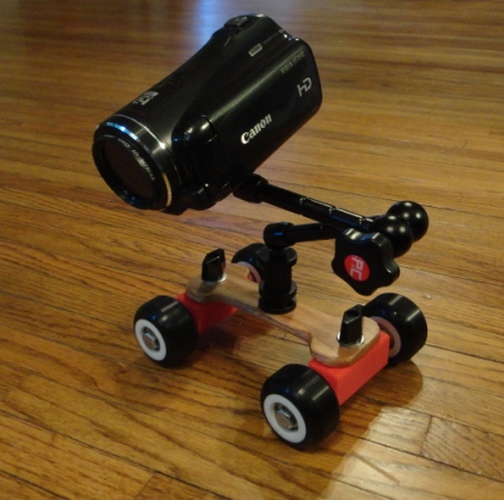
  In professional movie making the big guys like Spielberg and Lucas have unlimited budgets and they get to use the latest and greatest gadgets to make their movies really something special. This week I've completed a video camera dolly that is small, lightweight, inexpensive and easy to use.  It can be used on a table top and makes difficult video scenes a snap to make.  


 The video camera dolly was partially created using one of my favorite tools.... The Makerbot 3D printer.  The red axle supports between both sets of wheels were printed using this 3D printer.  Each section took about an hour to print.  


  The arm for the little dolly comes from a company named Pico and is purposely built for a dolly like this.  They sell their version of this dolly online (without the arm) for $100.  This was way more than I wanted to shell out for this little gem so I designed and built my version using the Makerbot for $22. The skateboard wheels I picked up on Ebay for $12 brand new complete with double sets of bearings no less and the rest of the hardware I found at Lowes for another $10. Quite a savings don't you think?

  
The arm for the dolly is special built and I did not even want to attempt to duplicate it as it is very unique in what it can do.  This and the fact that it only cost $28 to buy which I thought was a good deal.  To adjust the arm all you have to do is turn the knob with the "PC" on it and the arm unlocks.  It then can be positioned in almost any configuration that you can dream up to get you video camera pointed where you want it.  The arm is eleven inches long fully extended and is very well made and worth the money.


Here's a video demo that I put together showing you how the video camera dolly works and looks in action.  So pull up an easy chair and get your popcorn and soda ready.  All I have to do now is call up Spielberg and Lucas and tell them to stand back as I make my next epic video!

Sunday, December 11, 2011

Is It Real Or Is It Blender 3D?

  Over the past couple of days I have been busy once again at the QC Co-Lab maker space in Davenport Iowa making more parts for my Makerbot Semi Lowboy trailer.  Once I get a few more parts made I will post the latest progress with that project.  
  In the meantime I have been also working at home on the latest version of Blender 3D.  Blender is a great 3D software that you can download for free to create beautiful 3D graphics, full animation and even create your own games.  This software even has a full video sequence editing software built right into it. I use it to edit my videos complete with sound, title, and effects editing.  Great stuff. 
  I have been using Blender 3D for around ten years now and I also use it for concept work to see what a project may look like before I even build the first part.  I actually did this for John Deere for a time for a new concept that they wanted modeled up faster than what we had previously been using to design with.  
  Blender just updated it's render engine and so I am learning new things as I always am and have been having a ball with the latest version of Blender. Below you will find just a sample of what I have been up to.


 This first image is not a photograph but a 3D computer model I created using Blender's new render engine called Cycles. Pretty amazing to be able to create something that looks this real in a computer. The new render engine is not difficult to use.  Just a bit more steps to make it all do it's thing in the computer. 


This little guy on the trike is a concept idea that has been stirring in my head for some time now.  The vehicle started out as a pedal powered trike but now has evolved into what could be a full vehicle that runs on gas or electric power.  Check out the detail that Blender show in the rendering. Looks about as real as you can get without having it sitting in your garage.


  I wanted to see what the concept would look like for real and Blender now has made that possible without spending a small (or large) fortune to get there. 

  
In this image I was playing around with the front suspension and steering set up so the driver had room for his (or her) legs to be stretched out. The first version of this concept was more cluttered and not as clean looking as this one.


  In these two images you get a good view of the steering and suspension with and without the driver. This concept could be just a small commuter car or a even just a toy for a small child.  When using Blender the computer model can be saved and a new one copied and changed in minutes which saves a lot of time in making modifications to the design. My cargo trailer for my motorcycle (see photos elsewhere on my blog) was created this way.  This makes for an easier way to concept out a new design in a very short time.

  
 This is a nice top view of the trike concept. For now this vehicle is a fun idea but the concept has a long ways to go and still has a lot of bugs in it before I would ever consider building it for real.  But with Blender it gives me a good idea of what the finished vehicle (or at least the frame) will look like long before I decide to spend the time and money to actually put it on the road. 
   If you have not yet looked into using Blender 3D I suggest that you do so by checking it out and other images that I have here on my blog.  The software can be downloaded for free online by going to Blender.org for the latest version which now is at rev 2.60.  There is also a nice set of beginner instructional videos online at BlenderCookie.com which will get you started using this wonderful and fun tool to help you concept your next project. Worth a look for sure!
  

Thursday, December 8, 2011

Makerbot Semi LowBoy Trailer Construction Has Started


  For those of you who have not been following my blog for the past few weeks this entry will get you caught up with my Makerbot Semi build that I have been working on.  I have completed the assembly of the Semi tractor and the UFO (see earlier posts) and am currently working on printing out the Lowboy trailer for the complete model using the Makerbot 3D printer.  I have been compiling some interesting data on this build over the past couple of days.  So far the number of hours I have spent just printing the UFO and the Semi tractor has exceeded 80+ hours.  I have also gone over my computer model that I used to design the complete model and the grand total of parts in the model will be almost 500 pieces. The best calculation that I can make on the total amount of time it will take to print out the complete Lowboy trailer is another 60 hours.  But all of it is fun so it is another labor of love.


In this image is the computer model of the Lowboy trailer by itself. It is 23.8 inches long with a triple rear axles made from aluminum rod. With this trailer the total length of the Semi/Lowboy trailer assembly will be 30.5 inches long.


These two images are of the rear chassis of the Lowboy trailer with the axles and wheels mounted.  This will help you better understand the progression of photos to follow below.


The Lowboy chassis for the rear wheels is made up of three separate main sub-assemblies. Each section took a little over an hour to print and I was happy they turned out so well.  In black they are perfect for the build.


These "U" shaped connector pieces are what will be used to hold the three main sub-assemblies of the frame together. 


With two of the chassis sub-assemblies flipped upside down I slid the "U" connector over the two mating cross pieces and snapped it into place.  The fit was nice and tight and no glue was needed to hold it all together.  I designed mounting holes in the "U" connectors to run plastic filament through to hold this portion of the assembly together.  It was so tight that the holes were not needed.  You would break the parts if you tried to take them apart at this point so my design worked out better than I had hoped.


A very nice looking assembly and 3D print job at this point.


As before another chassis sub-assembly section is added to the build at this point with another "U" connector to make a nice clean looking rear chassis. 


  Very tight assembly with good stiffness.  The rear chassis portion of the Lowboy is complete at this point.  It is 2 inches wide by 5.5 inches long.   As pictured it is only 1.5 inches tall.  Not a big assembly but nice detail just the same.  


  Here I've added the axles that will be used in the trailer.  They were made from polished 1/4 inch aluminum rod and cut to 4.5 inches in length.  The tips of each rod were then drilled out to accept a cotter pin to hold the dual wheels on each side.  With having to print the twelve wheels for the rear chassis assembly it will take roughly another 15 hours of printing on the Makerbot.  I will hold off on that portion of the build until the very last of  the assembly of the Lowboy.  All the wheels will match on the Semi so it will look really good.  Look back at some of my earlier posts to see the Semi tractor build and the completed photos of it with the completed UFO. 

Thursday, December 1, 2011

Makerbot Semi Tractor Is Completed After Marathon 40.73 Hours

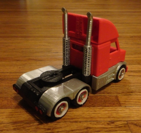
  After what seemed like months, today I have completed my Makerbot Semi Tractor.  I counted up the hours and it comes to a staggering 40.73 hours of printing.  This total does not include the design time nor the assembly time to put this portion of the model together.  But I am not complaining in the least as it has been a lot of fun so far creating this little beast.  The Semi at this point stands 7 inches tall, 4.5 inches wide and 10 inches long. The following photos show the wheels being installed and the photos of the completed Semi now has the air dam on the top of the roof also installed.  The air dam alone took four hours to print.  But I think it was all worth it.
 

  In this photo are two of the three axles that I made using 1/4 inch aluminum rod.  I drilled out the ends of the rods so that a cotter pin could be installed in the axle to hold the wheels on.  This made for a much stronger assembly though I think the Semi could still be done using wooden dowels and then just glue the wheels on to the axles. A small end cap was originally designed for this purpose but again I thought the aluminum rod was a better way to go.


Lots of parts for the wheels had to be made for this porion of the assembly.  Each wheel is made up of three parts.  The tire, an inner hub (either red or black) and a white rim.  It was a very tight fit which was like snapping Lego block together..... no glue was needed as it was a very good fit.


This is a good shot of the front wheel with the cotter pin installed.  I added a small washer behind the cotter pin so the wheels actually roll.


Here I am test fitting the rear dual wheel assemblies for the Semi.  This part of the build was easier than I had expected and that is always nice to have happen in a big build such as this.


The wheels really dress out the Semi with the red inserts and the white rims!


I really like the red tail lights in the rear bumper of the Semi.  A lot could be done with this model as my friend Neil had pointed out that I could have put LED headlights and tail lights in the model.  I told him he can do that when he builds his Makerbot Semi. 


These two photos give you a good idea of how big my completed Makerbot UFO and Semi really are.  The UFO is 10 inches in diameter.  I had not posted photos of the completed UFO so if I missed it here it is again.


  The original UFO had a Makerbot solid printed dome on the top.  I replaced this with a clear plastic dome and a complete interior with seats, controls and instrument panel.  Makes for a much more interesting model.
  Next on my plans for projects will be Lowboy trailer that will go along with these two models.  The completed model of the Semi with the trailer will be 30.5 inches long and have a special carrier on the trailer that will enable the UFO to be carried on it.  I think the trailer will be simpler to assemble than the Semi tractor has been but the amount of time to print it will also add up very quickly.  This should be interesting to see how it all turns out and the number of total hours it will take to complete this large model.  I'll keep all of you up to date on my progress so keep checking in from time to time and you'll see my progress.