Monday, March 4, 2019

3D Printed Three Bladed Boomerang Project!

Roughly fifty plus years ago when I was just a kid in school I enjoyed playing with a toy that no longer is on the market.  This was a three bladed boomerang produced by Ohio Arts.  I am not sure if the company even exists today but I do remember the toy very well and thought that it would be great if I could find one.  I went online to see what I could find.  I only came across a couple of postings about the toy. One was an article about it and the comment that one had sold on Ebay for $200.  I then found the toy on a site called Etsy.  Here the seller also wanted $200.  I remember this toy only costing me a couple of dollars.  No way am I going to pay that kind of money and I knew that I could make it maybe even as less as what I paid for it as a kid. Another project presented itself once again.


The photo above shows what I had recently come across on Etsy.  This was called the HiYo boomerang.  It flew like a regular boomerang and I remember that you needed a good sized baseball field to fly it.  It was a lot of fun but there is no way that I would want to pay more than a few dollars for one even today.


I did remember that the original boomerang wings had an airfoil shape like what is on an airplane and with the information that I had gleaned from the Etsy site found out the dimensions of the wings as well.  It was at least a start.  I did a little more research online to find a suitable airfoil shape.  The diagram above gives you just an inkling of the different types of airfoils shapes that are used in aircraft.  The bottom shape called the Actual Clark Y was what I was looking for. 


As I usually do I started my design work using Fusion 360 CAD software.  The image above is what I came up with.  I knew that the distance of the original boomerang from tip to top was 12.5 inches.  Again this was valuable info as it made laying out the new design much easier to work out.  I took the original boomerang photo from Etsy and scaled it to the 12.5 inch tip to tip size.  From there I copied the airfoil shape on the tip of the layout and again near the center of the new boomerang design.  After this was completed I simply lofted the airfoil sketches to form one of the wings.  I knew at this point that the shape of the wing looked good.  

Next I took the first wing shape and made a circular pattern around the center axis of my computer model.  This gave me the three wings I needed for the toy.  After some cleanup of the model to get the nice smooth shape where the three wings overlapped I combined all three parts into one body or component.  I decided to make a recessed triangular area in the middle of the toy and insert an additional triangular part with a star cut out in the middle just to give it a little Tinker's Workshop style.  


Here is how the finished boomerang looks this morning after 3D printing, sanding, and painting was completed. This is actually the second test model.  The first model I 3D printed worked right out of the box on the first throw.  The only trouble was that my back yard was nowhere near big enough to fly the first test model.  (My mistake.) With the first throw I made the boomerang immediate made a 180 degree turn, flew over my garage and to this day I still have not found it.  Luckily I did not 3D print the first test model full scale.  That boomerang along with this latest one is only half scale being eight inches in diameter. It was much quicker to make it this size and if it failed would be easier to try and correct any design flaws to make another test boomerang.  

My 3D printer will be able to make the full sized version which will be sixteen inches in diameter if and when I find that the second test model flies as well if not better than the first test version did.  I will test the second model out in the next couple of weeks when the weather starts to warm up a bit and I can get to a baseball field that is near my home. (Seven below zero out today....ouch!)  At least there I can give it a good throw and still be able to see where it lands so I don't loose this boomerang like I did with the first one.  If it all works out I will then 3D print the full sized version that takes over nine hours to 3D print.  I'll let you know how it all turns out.   Have a good one!

Wednesday, February 27, 2019

Creality CR-10 S4 Filament Spool Stabilizer Project

I finished this project a few weeks ago and am finally posting about it now.  On my Creality CR-10 S4 3D printer I found that once in a while when I am making something that the standard support for the spool of filament begins to vibrate more than I would like.  This vibration is caused by the printer itself and the part it is making.  When the head of the printer gets into a rhythm in the "Y" axis (a forward and back motion) that starts a vibration on the spool holder which increases the vibration even more.  Not a good thing to have going on while 3D printing. So this project came to be. 


The spool of filament rests on a horizontal shaft that is mounted to an arm at the rear of the control box for the Creality CR-10 series printers.  This shaft setup seems to work fine other than the problem that I have come across.  The vibration is caused by the resonance of the printer and is amplified by the spool hanging on this shaft. 


To eliminate the resonance started by the rhythm of the printer I created the stabilizer for the shaft of the filament spool pictured above.  It took me a couple of tries to get the alignment of the hole for the shaft and the "C" shaped form at the bottom of the stabilizer to line up correctly but it has been worth the effort.  I printed the part using ABS filament with only a 20% infill.  This part did not need to be very solid to do it's job and over the past few weeks I found this amount of infill to work very well.


With the stabilizer in place it has eliminated the resonance of the printer and just put my mind a little more at ease while running the machine. To install the stabilizer is a simple task of removing the large retaining nut on the end of the filament spool shaft and then sliding the new part onto the shaft and over the top of the control box as pictured above.  The retaining nut is then reinstalled and it's ready to use.  There is more than enough room on the shaft to have the stabilizer and spool together without any binding. 


Here's a couple of good shots of the stabilizer installed on my 3D printer control box.  I printed it in black to blend in with the rest of the components for my 3D printer.  Of course any color would do just as well.  It was just a matter of personal preference at this point.  I am just happy that the new addition to the printer is working out very well and has cured one more issue that I felt needed to be addressed. If it makes 3D printing parts easier than I am all for it.

Monday, February 18, 2019

Multi-Colored Parts Test Project Using Cura Software

This afternoon I put together a small test project that has been on my mind for some time.  The idea for the project came together a couple of weeks ago when I found a video on YouTube on how to make multi-colored parts on my 3D printer that has only one extruder.  I liked the idea and saved the video to my computer for future reference.  More about this in a minute.

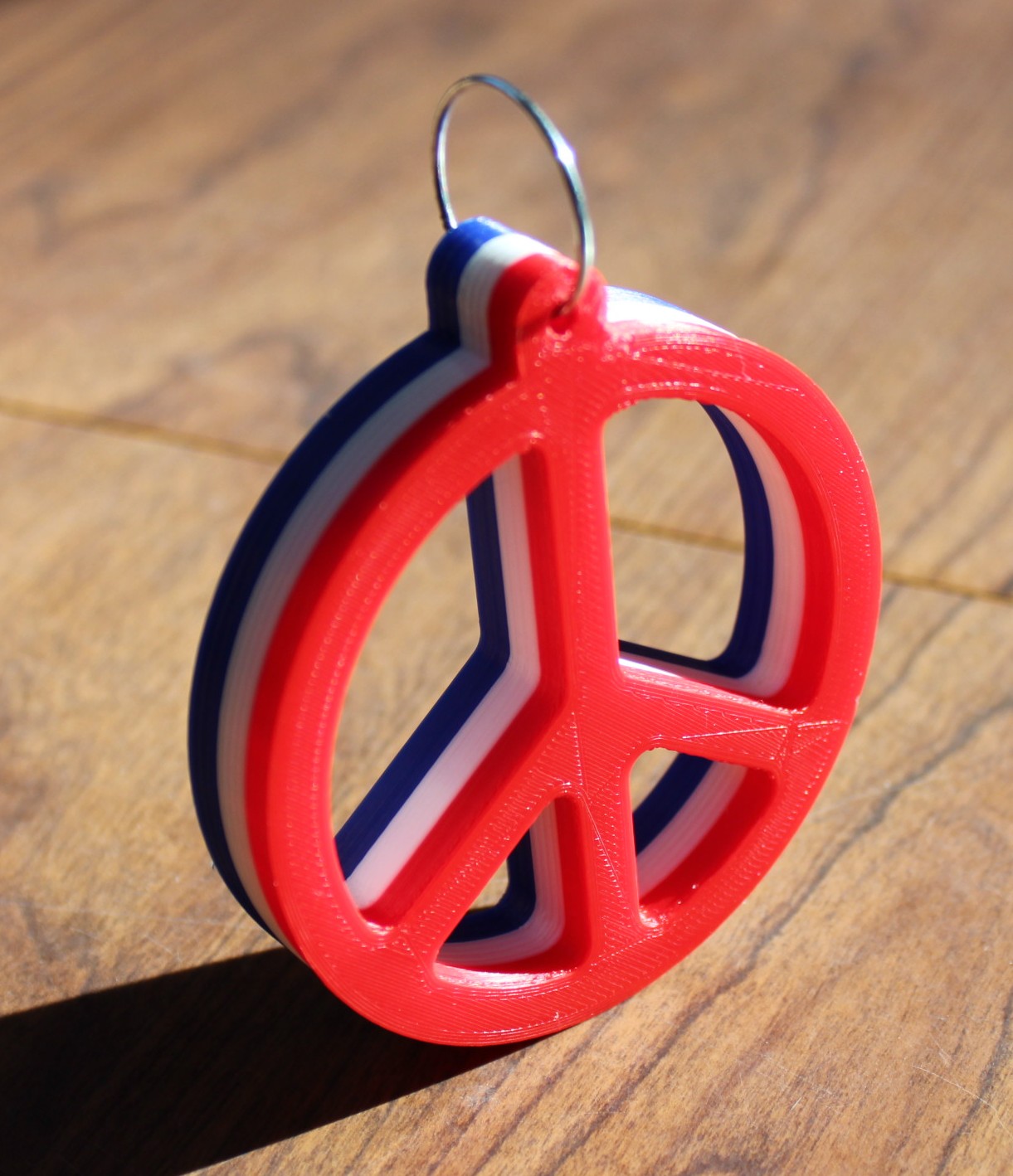
A couple of days ago I got to talking with my sister about my 1970 dune buggy that I have been making several projects for and thought one thing was missing.  A peace sign hanging from the rear view mirror.  With that idea along with the multi-color 3D printing video this little test project was born.


With the project being a peace sign I knew that I had to make it red, white and blue.  Pictured above is how the little sign turned out.  With the video that I had found on YouTube I was able to make the necessary changes to the G-Code in Cura slicing software for my 3D printer so that it would pause after each layer of colored filament had been completed.  I designed the peace sign using Fusion 360 and made it so that it was .60 of an inch thick over all.  The diameter of the circle is exactly three inches.


I did not want the peace sign to be to large so I thought that it would be about the right size at three inches in diameter.   I started with the color red first on the 3D printer and after it had reached .20 of an inch in height it paused so that I could change the filament to the color white.  The first time I had tried to print the part I had the wrong filament in and so I had to start over.  I thought I had red in the machine but it did not look right.  It looked more orange than red so back to the beginning.  Luckily I had a new spool of bright red ABS filament sitting next to my machine so it was not a major setback.


Once I had changed to the white filament for the second part of the project I just let it run until the next pause came up on the printer.  I finally added the blue filament and as you can see from the photos it worked perfectly.  When the 3D printer paused so that I could change filament the extruder moved to the center of my print bed so it was out of the way.  I then changed filament after which I went back to the control panel for my Creality CR-10 S4 printer and told it to resume the print.  The printer then came back up to the correct temperature to print the following layers  and it matched everything up perfectly.  A no brainer so to speak to make it all work out as well as it did.


The perfect place for the peace sign.... the rear view mirror of my dune buggy.


Here's the link for the video from "Frank's 3D Shop" on YouTube to show you exactly how I made my little peace sign. It is an easy video to watch and follow so you should have no trouble in making multi-colored parts on your 3D printer just like I did without having to have a dual extruder on your printer.  Good luck!

Wednesday, February 13, 2019

Mind Boggling R/C Model Making..... "I'm Not Worthy!"


I was doing some work in my workroom yesterday and while I was 3D printing some large parts I was also surfing on the Internet as I usually do.  This kills some time while waiting for the 3D printer to complete whatever part it is making.  While killing time I came across an amazing video of a radio controlled model truck being constructed.  Various materials were used in this 1/6th scale 1961 Dodge D100 pickup which was crafted by Konstatin Bogdanov. All of it built way beyond my skill level.


One of the main things that peaked my interest in this video was that the truck was designed using Blender 3D.  Not a design software in any sense of the word and not my choice of software to design anything but this has led me to look into the process further to see how it was done.  After watching the video my eyes have been opened as far as the design work goes. Then the build was started and I was further blown away by the expert skill level of this amazing modeler.  


I usually get comments from people I meet about the projects I build that amaze me by the responses that I hear.  I classify these comments as the typical "I'm not worthy! I'm not worthy!" type of response.  So I have no hesitation in saying  the same for this builder of this model truck with all honesty I have to say "I'm Not Worthy!"   Check out the video and you will understand why I bow down to this amazing builder and give him a standing ovation for his modeling skills.

Friday, February 8, 2019

A Blender 3D Mini Cooper and A Little Green Alien

With all of the cold winter weather keeping me indoors the past couple of weeks I have been keeping busy once again modeling with Blender 3D.  Also since I thought I better get another posting out to keep all of you up to date this makes another good subject to write about.

As most of you already know I drive a very nice little 2014 Mini Cooper.  It has been one of my goals for a long time to model my Mini in 3D using Blender 3D.  I finally bit the bullet this past week and got started on this project.  Like most of the vehicles I model I know this will take some time as it usually takes me around 100 hours or so to complete any vehicle that I put a large amount of detail into using Blender.  I suspect that this will be the same with my Mini Cooper.


As with all of the vehicles that I model in Blender I start by tracking down as many images as I can of the car or truck that I am working on.  I am fortunate to own my little mini so I have a good reference point to start the project.


I also rely on a lot of images that I can find online.  The photos above work out very well to get the details of the vehicle to the right proportion when setting up the model in Blender.  So a lot of research goes into setting up the model before I start modeling.  Again the plus side to all of this is the fact that I own the car so I can get a close up view or photo of something on the car to get the detail exactly right.


Here's a good example of what one of the front headlights for the Mini looks like up close. It's the little details like this that I want to get into my Blender model and usually this is what makes the completed model stand out from the average looking model. 


Here's a good start to the front hood of the car.  I play around with the color of the car early on just to get an idea of how the completed model will look when I am done.  I feel pretty good about the color at this point so I can check that off of my to do list for the model.  The shape of the hood also at this point looks good as well.  But with all of my Blender modeling it is tweaked over and over again until I am completely happy with the end result.


After a bunch more hours work the lower front of the car is starting to take shape.  It can get frustrating at times when a model just does not seem to fall into place.  At that point I leave it sit for a couple of days and then go back at it.  This morning the lower section that I thought I would not get laid down to my liking started to finally take shape.  It still needs a bit more finessing but I am again happy that I am getting it worked out.  Progress is being made and that is always a good thing.  That is where I am at this point this morning anyway with the Mini Cooper Blender model.


Now for a completely different Blender 3D model pictured above is my version of a little green alien. I had modeled this guy years back and wanted to put more detail in the model but had lost him due to a major computer failure.  I ended up losing this little guy along with a lot of other Blender models that I had worked on over the years.  Luckily a large portion of the images to these models still remain so at least I have that much.

I had tracked down the instructional video that was put out nine years ago and decided that I wanted to recreate this little character once again. Here is the link for the video instructions on how to make your own little green alien.  


Some time down the line I thought it would be great to animate this character and with the instructions that I found to create what you see here the alien is laid out very well. He should work perfectly if I do want to animate him.  Another idea I had was to modify this little guy to give him two eyes instead of one and maybe put some green fur on him.  Both are easy modifications so it would be fun to play around with him to see what else I can come up with.

Also before I end here I wanted to let you know that the tutorial to create the alien is very easy to follow even for Blender 3D beginners.  So look into it. I think you will enjoy making your own little green alien. Have fun!