Sunday, November 25, 2018

The Dune Buggy Has Arrived!

As usual lots of things have been happening here at the workshop so my postings get a bit delayed.  But this posting is worth the wait as my new (old) dune buggy has arrived and is now safely stored in my garage. The dune buggy started out as a 1970 VW Beetle.  A gentleman in Tucson Arizona took six years to build it.  He then sold it to another man in Florida who had it for a few years and then I now own it.  It only has 2200 miles on it.  The underside looks as good as the topside.  Not a mark on it anywhere.  I am amazed and proud to call it mine.


Isn't she a beauty?  I am so tickled to finally have it here so I can keep it out of the winter weather and work on it all at the same time.  In an earlier post I was looking at enclosing the storage area just behind the seats so the I could lock things away when the dune buggy was left parked somewhere.


This is what I had in mind.  But like all ideas, plans sometime need to change.  This actually was the case with this idea.


Behind the seat is a very nicely padded vinyl covered deck with a small "T" handle at the front just between the seats.


The "T" handle opens up this deck to have access to the battery that is just behind the passenger's seat.  On the opposite side behind the driver's seat is a small storage area as well.  The only issue I had with this is that the deck lid did not lock.  I tried to remove the entire deck but was not able to being as it looks like the deck was installed before the body was mounted to the frame of the car.  So I could not remove the deck and in not being able to the idea of making an enclosed trunk area went out the window. 

So the next best thing and the simpler idea was to put a lock on the deck itself.  It would still give me a safe place to store at least smaller items and be much simpler to accomplish than designing and building and entire trunk. 
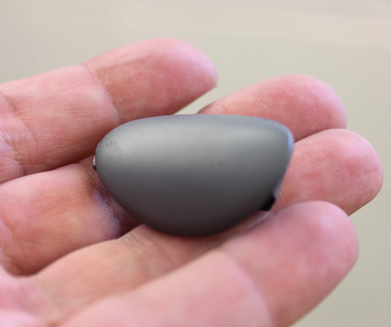
That lock that I needed for the deck to secure it was a cylinder lock like the one shown above.  The deck itself is made up of 3/4" plywood with a 1/2" of foam padding covered in black vinyl.  It was very well made so I did not want to destroy it by installing this lock.  That was the first goal to be sure. The issue I had was that the lock had to function properly but I did not want to have to jump through flaming hoops to get it installed. 


When the deck lid is closed it rests on a wooden support just behind the seats.  This again was made very well so I did not want to hack it up just to put a lock in.  What I figured would be the simplest thing to do is to recess the lock so that the metal latching arm would rotate underneath of the front wooden support.  I made a test part first just to see how I would accomplish this task.  

In the photo above you can see a small piece of wood that I cut a 1 1/2" diameter counter sink into and then drilled out the center to 3/4" to receive the lock.  This looked to be what I needed but this was done on a drill press and I could not do the same with the deck lid as it could not be removed from the dune buggy.


I first drilled a pilot hole through the underside of the deck lid making sure to mark the exact position of the center of the lock.
In order to keep my pilot hole perpendicular to the underside of the deck I first drilled another pilot hole through a small piece of scrap wood on my drill press. This I then used as my guide to keep my drill aligned properly to the underside of the deck lid.

 Once the pilot hole had been drilled into the deck lid I then marked a circle with a Sharpie where the vinyl on the top of the deck needed to be removed. (Scary to say the least).  Now with the vinyl out of the way I again drilled a counter sunk 1-1/2 inch diameter hole only down 3/8ths of an inch.  I worked slowly and as I did not want to mess this up.  After the large counter sink was finished I then drilled the 3/4 inch hole for the lock.  Clean up the wood chips from my drilling was next and I was able to mount the lock as shown above. 


With the lock installed I tightened up the nut to secure it and it looked good from the underside.  I closed the lid and it locked and unlocked perfectly.  I could breath again.  


The next step was to clean up the look of the recessed lock on the top side of the dune buggy deck. This was the simplest part of this project.  I wanted a nice clean look to the installation and I did not want to compress the foam and vinyl in the process.


I designed this simple ring using Fusion 3D CAD software that would be inserted into the 1-1/2 inch diameter counter sink that I made for the lock.  I then 3D printed the part, sanded it smooth, primed and painted it gloss black. It turned out great. 


Then it was just a simple matter of sliding the part into place to finish off the installation of the lock.  The lock looks kind of deep but the key goes in easily with more than enough room to turn it and remove it so it is all good.  I really like the look of the gloss black paint.  I did not glue this part in place as it is a friction fit into the countersink for the lock.  I thought this way if this little ring needed to be repainted it would be a simple task to remove it and spruce it up and reinstall it.  If it was glued in there would be little hope of making it look like new again.

Now I have a lockable storage space for the dune buggy.  Not a large space but at least large enough to throw in a camera, jacket, my lunch and maybe even a small cooler. The cooler idea I have done for my motorcycle so I know I could make a custom one for the dune buggy as well.  Anyway I am happy that this addition to the dune buggy has worked out very well and will be a welcome addition to using the car. 

I have a couple more projects for the dune buggy that I will post about as I get into them.  Hope your latest project is going good for you as well. 

Saturday, November 24, 2018

Half A Million Visitors To My Blog! Time To Celebrate Again!

This week my blog has reached a major milestone with having had over a half million visitors since it's conception. I never dreamed that the blog would last this long much less have a worldwide audience to have visited so many times.  The number of visitors varies week by week and month by month but to still stir interest after all this time is amazing and gratifying all at the same time. 

I have received countless emails from readers over the years thanking me for writing the blog and showing everyone what I design and create in the workshop.  Not to mention the problems that occur from time to time that I figure out how to solve to complete a project.  It's a labor of love  for sure and with having all of you support my blog it renews my spirits when I am down and gives me a great feeling to know that I have so many friends that enjoy seeing what I am up to. 

With that in mind I want to thank you for sharing this journey.  It has been very rewarding to make the things I do but even more so to hear from you and help you with your projects along the way too.  It has been a great ride so far and I can only hope that things will continue for a number of years to come.  Thank you for all the visits and I'll try to keep up my efforts to show you bigger and better projects in the future. 

Friday, November 16, 2018

3D Printed Camera Slider With Stabilizer Is Completed

I am very happy to report this morning that I put the finishing touches on my 3D printed camera slider with a new stabilizer arm. This along with a little more tweaking of the electronics finished out the project very nicely.  With the electronics I had missed putting in an on/off switch so the battery was being used even though the slider was not actually moving.  An oversite on my part.  So let me show you how it all turned out.


Here is the new setup.  With the addition of the stabilizer arm that extends from the right side of the camera slider to the tripod the slider now is no longer like a teeter-totter.  It has taken this flaw out of the slider and is now very rock solid.  This addition also was no extra cost to me other than a couple more 3D printed parts for the 3/4" x 16.5" long aluminum tubing to mount it along with a modification to the underside of the right side tripod mount for the slider. 


A key component that I luckily had in my stash of miscellaneous parts in the shop was this photography jaw clamp.  This is quickly and easily added or removed from the tripod and securely clamps to one of the legs.  Once I had discovered that I had this part it was just a simple task to work out the rest of the stabilizer in Fusion 360 and 3D print the needed parts.


Next I had to figure out where I should install the on/off switch for the electronics.  I originally wanted to mount it to the back side of the slider but this would involve possibly having to reprint the entire housing if it did not work right out of the box. If I drilled through this housing it could go all wrong and I would have had to reprint the housing which would take another 11 1/2 hours to make.  Not something I wanted to risk.  So instead I opted to putting the switch on the housing cover.


Again I already had the switch in my spare parts and it was back to Fusion 360 to make sure there were no issues inside the electronics housing.  I simply drilled out the hole for the switch, worked out a little more wiring, mounted the switch and label and called it good. With choosing the cover instead of the main housing for the switch I could risk messing it up by just drilling the hole for the switch. If it failed it would have taken a lot less time to reprint a new housing cover.  Now I know when I want to use the camera slider I will have a good battery when it is needed.


I wanted to add this image to my earlier post and forgot about it so I thought I would post it now.  This is a good image from Fusion 360 of the inside of the electronics housing.  At the very top of the housing is the geared 9V battery powered motor.  By the way works very well.  Inside the housing on the lower left you can see the 9V battery and inside the main cavity of the housing is the electronic circuit board that is the controller for the motor, motor direction and speed.


Lastly here is a good shot of the back of the electronics housing.  The large on/off/on switch  controls the movement of the camera slider for either left or right movement.  The knob just below this switch controls the speed at which the camera slider moves the camera along it's track.  

So that's about it. The plus side to the stabilizing arm for the slider is that I can adjust the camera slider up or down with the tripod center shaft. I only have to reposition the stabilizer arm on the tripod leg to make the slider rock solid once again after this movement.  All of which takes only a few seconds to accomplish.  It will be a nice piece of equipment that should help make some interesting video shots in the near future. 

Thursday, November 15, 2018

What A Bargin..... A $50 Mini Cooper Part For Three Cents!

As most of you already know I am a big fan of Mini Coopers and I am happy and proud to say that I own one.  A great little car that looks great, drives great, and gives me exceptional gas mileage.  With all of that what could be bad about it? Right?  Well I found out this week when I had a very small part disappear from my car.  On the drivers door handle of my 2014 Mini Cooper is a small plastic cover that hides the opening where a key would normally be used to open the door.  This opening on my car is still there it is just covered up and only used in case of an emergency where the battery powered remote had a dead battery and you still needed to open the door. The small plastic cover would be removed and then an actual key that is already built into the remote can be removed and used to open the car door.  To my surprise this week I found out that this little cover had gone missing. 

Somewhere in my travels over one day it simply fell off of the car. I did some searching only for the nearest Mini Cooper forum and sure enough this is a common occurrence. Other owners like me have been complaining about this part falling off of the car as well.  Not a good sign.  

So I called my local Mini Cooper dealership and inquired about this little plastic part that is no bigger than your thumb to see if I could get a replacement.  To my astonishment I was quoted a price of $48 (plus tax) for a grand total of $50 for a little plastic part.  I turned the offer down and told them that being a retired industrial designer and owning a 3D printer now was the order of the day.  The gentleman at the parts department agreed with me whole heartedly and so my mission for that day was clear.  Make a new part!


This is what my door handle looked like with the little plastic cover now missing.  Not a pretty sight to be sure. My original cover was black and so I had that bit of information to start.  The passenger 
door did not have this cover so I could get a good close look at it and possibly take measurements. So I had to start from scratch.


These images of chrome covers that I found online were exactly what I was looking for.  But no way was I willing to pay $50 for a piece of plastic around the size of your thumb!


Here's another good shot from online showing you exactly what kind of scale this part is to the car as well as someone's hand.  On one end of the cover is a small tab and the opposite end is a small raised bar.  All plastic.....no metal.


After three or four tries to get the outer cover shaped to match the handle I came up with what you see here.  I 3D printed the part and fit it to the opening in the door handle.  It looked to be right on for shape and size so I pressed on.


Here's view of the underside of the cover.  This had a simple "L" shaped configuration with a small wedge on one end.  To get the locking mechanism to work I printed the "L" shape without the cover first so I could see what was going on.  This again took several tries and so the last step was to combine these to parts into one.  This was a simple matter of using Fusion 360 CAD software and dialing in the part to have it print all in one piece.   Once I had the part 3D printed I wet sanded it smooth with 600 grit wet/dry  sand paper.  Then I primed the part as you see in the photos above.


After the primer had dried properly I wet sanded the outer face of the cover once again and finally added a couple of coats of gloss black spray paint.  


Lastly when the part had dried for 24 hours I took it out to my car and carefully slid the part into place with a nice steady pressure.  The part went "Click" and looks to be secure. Just to make sure that the new cover will not also disappear I added a very small amount of silicone sealer to one end of the underside of the cover. A very small amount.  I will keep my eye on my new cover over the coming weeks to make sure I have this all dialed in the way I want.  But for right now I think I have the best replacement part in the world when I can 3D print it and only cost me 3 cents instead of $50!  Plus the fact that if ever I should loose this one I can do a bit more tweaking to the design to improve upon it if I have to and reprint a new part in less than an hour.  Works for me every time!

Monday, November 12, 2018

3D Printed Motorized Camera Slider Project Nearly Completed!

Like most projects that are started and finished here at the workshop delays, changes, new ideas and what have you seem to creep into the original design. Not that this is all bad but when I start a project I always seem to want it to be finished faster than it actually takes. Sometimes this works out better than I hope for and other times worse.  

This has been the case with the 3D printed camera slider. But that is neither here nor there now that it is completed.  This has been an interesting project that has had many revisions in the design to improve it and make it easier to build and also use.  So I am happy now to show you the finished project and what it can do when shooting video.


Here is the motorized camera slider by itself without the tripod mount or video camera.  The camera slider is very light weight at only 2 pounds 6 ounces. The extruded aluminum rail is the key to the assembly which makes the slider very light weight and sleek looking.


In the upper photo you can see the enclosure for the electronics on the far right that make the slider move both left and right with a variable speed control.  All of this runs on one 9 volt battery.  In the bottom photo is the camera slider platform where a video camera or DSLR camera is mounted using a quick release mount. Under the platform are three rollers that are mounted in a "V" configuration and glide smoothly along the extruded aluminum rail by use of a small electric motor and attached drive belt.


Here's a good view of the control box for the camera slider. At the very top you can see the small battery powered motor that makes the slider move.  Next just below it is the double throw on/off/on switch to power up the slider and change directions either left or right.  Lastly at the base of the control box is a knob to control the speed at which the camera platform moves along the extruded aluminum rail.


At the opposite end of the camera slider is a simple guide wheel for the toothed belt that runs from the camera platform to the motor through the upper portion of the extruded aluminum rail around the guide wheel and then back to the camera platform. 
\

Here's a good shot of the camera slider tripod mount.  It took me a bit to get the center mount designed and 3D printed.  Ten and a half hours for the center piece alone. The tubing is 3/4 inch aluminum tubing and the end mounts as with the rest of the project have been 3D printed. The mount is very light weight so that is a plus with the project.


Here the camera slider is completely assembled with my video camera set up as well. At this point I still have to shoot some video to test out the assembly and the only issue I think I will have at this point is stability using a single center mount.  I will explain about this in a minute.  All the electronics that are inside of the control box on the right have been tested and everything works so far so that is a good sign. 


The center mount locks into the tripod nice and firm but I am still thinking about changing this to end up using either two tripods instead of one or having at least a stabilizing arm to support one of the far ends of the slider.  Mainly because of the weight of the control box on one side and the additional weight of the video camera or my DSLR camera I think I will have balance problems. The overall travel that the slider has is 28 inches.  This makes things a bit tricky with the camera weighing a couple of pounds and being moved to the far ends of the assembly.  Two tripods which I already  own will solve this issue in a quick hurry but would be a bit of a hassle to use when shooting. So I think a stabilizing arm will have to be incorporated into the design to solve all of this. 


The entire assembly looks very professional so that is a real plus with the camera slider. Total cost came to right around $60 which is a far cry from the cost of a professional camera slider that can run into the hundreds of dollars. I will take that any day.  

As I said earlier I have not had a chance shoot some video with this camera slider yet to show you what it does but I do have video that I shot some time back with another camera slider that I designed and built.  This will give you a good idea of how this equipment works and what the end result looks like.  Click the video below to check it out. 


I will be working on the stabilizer for the tripod mount over the next few days so stay tuned for that update.  As I said earlier about changes and delays in my projects? It's holding true to form on this project. This one has just a bit more fine tuning and then hopefully I can be completely happy with the end result.  I'll let you know how it all turns out.