Wednesday, May 22, 2019

1/6th Scale 3D Printed 1927 Bugatti Type 35 Model Project Part 5

I've spent at least a couple of hundred hours these past few weeks in the designing of this Bugatti Type 35 model and am finally getting to making parts for it on my 3D printer!


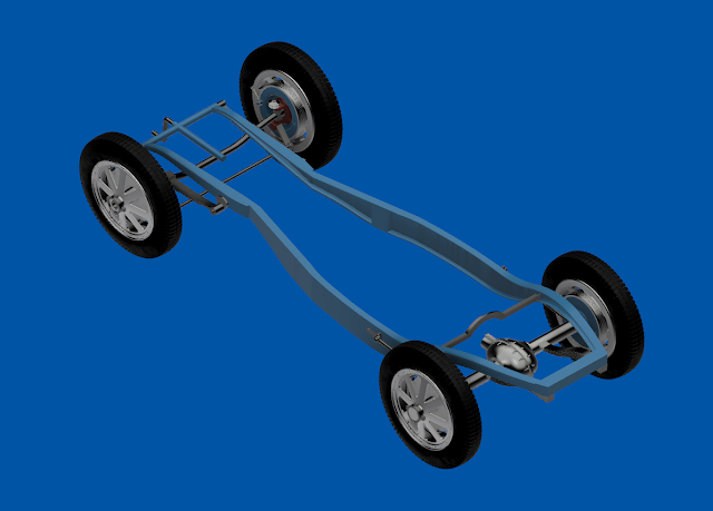
I am also very pleased with the images shown above that I created using Fusion 360 CAD software. Looks pretty much like the real car so that is a good start anyway as far as getting a model of the car built that looks as correct as possible.  At least as correct as I can make it without having the engineering drawings to make it absolutely perfect. 


Shown above are the components that are needed to make up the frame along with the floor and lower section of the engine compartment. The four long pieces at the top of the photo are the rails for the frame.  I needed to each of the two rails in two sections as my 3D printer could not make them all in one piece without making the entire model in a smaller scale.  Not something I wanted to do from the start. 


Here is the floor of the car with the center hump for the driveshaft and the mounting holes for the seat supports.  I was happy that this part turned out so well as it will be one of the main features to see in the model once it has been completely assembled.  The larger hole in the floor will be needed to mount the dual mufflers in the model.  All of these holes will be covered up by the seats so they will not be seen again after assembly.


Here the frame and floor have been test fit together to make sure everything lines up correctly. The panel setting next to the frame is the underside view of the engine compartment.  The model's engine compartment will not have the capability to be opened up so I did not bother with trying to design the engine for it.  The underside of the engine compartment had to be simplified to fill the space where the engine would be along with a mounting area for the dual exhaust.  This part will be installed on to the frame once it has been glued together.  


Here is another look at what the frame will look like once the axles and wheels have been add to the build. Total time to 3D print the parts I have shown here came to around 79 hours. This seems like a lot but the best I can estimate to 3D print the entire model will be right around 200 to 300 hours or more.  Then add in another 200 hours or so for the design work and your now looking at a 400 to 500 hour build. 

 It all takes time both on and off of the computer.  Hopefully in the coming weeks I will be able to get more 3D printing done on this 24" long Bugatti model. It should be a nice display piece when I get it all put together. 
Monday, May 13, 2019

The Indian Motorcycle Logo Sign Project Part One

Way back when I started this blog I put out a post about something I had created in Blender 3D software.  It was of the Indian motorcycle logo sign. I thought after all these years that now was the time to actually make the sign I only dreamt about all those years ago.

This is a copy of the image that I had used to make my Blender 3D creation way back in 2011.  I wanted to make a very large sign at the time but never got around to either finding the time or the money or the space to build it or display it properly.  So I settled for the Blender 3D version.


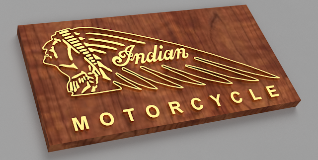
Here is my Blender version of the sign and I am still very proud of what I created.  It would make an impressive sign in chrome plated steel on a wooden base as you see here but it probably would be very difficult to make as well as expensive on top of it all.  I simply do not have that type of talent when it comes to shaping metal so I never attempted to make it this way.  


With this project in mind I recreated the sign as you see it here using Fusion 360 CAD software. Instead of chrome plated steel I thought I would try and make the sign smaller and the intricate parts by 3D printing them on my 3D printer.  The sign would be 16.5" x 8.5".  I would make it bigger but my 3D printer would not be able to make the Indian head perimeter that large.  As you can see from the image above the perimeter is all one piece so that is the issue with making it on my 3D printer.

In the image above I used a wooden base which looks very nice and being smaller in size would not be a big issue with trying to hang I on a wall when it is completed.  It will be easy enough to cut a piece of wood to that size and varnish it.  The real trick is how to attach all of the pieces to make up the sign once the wood has been cut and how to locate all the piece in the correct orientation that you see in the image.  Something that I will have to work out further before I actually start making parts. 


I also thought about having a gloss black base instead of a wooden one.  But after comparing the two images that I have here I am leaning more toward the wooden display due to cost as well as the over all look of the sign.  I think the wood looks a bit warmer than the all gloss black display.  Both have their merits so it is something else that I will have to consider further on this project. 


I did manage to track down some very nice gloss brass colored paint today.  I took one of my reject parts from another project and painted it to see how it would turn out.  As you can see from the photo above it sure looks like brass to me.  So to paint all of the parts for the sign with this paint has got my vote to continue on with this project so far.  

All of the parts for the sign would be sanded smooth so that the finish would be even better than the un-sanded part that you see above.  In the mean time I will start tracking down the wood that I want to possibly use for sign as well as the gloss black acrylic.   The plus side to the acrylic base it that there is no need to sand or varnish this part for the sign.  It would save time but not sure if it will keep the cost down just yet.  Will have to do my homework on all of this before I decide my next plan of attack for this project.  So far it looks promising though just the same.  Stay tuned for more on this project in the coming weeks. 

Monday, May 6, 2019

Dune Buggy Wind Deflectors Project Is Completed!

Another banner week here at the workshop with putting the finishing touches to the dune buggy wind deflectors project upgrade and completion. No major issues with the changes that I had made to make the deflectors stronger and smoothing everything out to give all the parts a nice glossy coat of black paint.


As before with my earlier version of the wind deflectors the new upgrades that I had made did not detract from the look that I was going for with the design.  In the photo above the deflectors are pretty much invisible.  


The mounts now are much stronger because of the internal brass rods that I installed into them and they are thicker as well.  I had originally thought that I would paint the mounts red but with them being glass black they blend in very well with the rest of the cars interior roll bar and seats. 


Here's a good look at the lower mount for the driver's side of the dune buggy. I am happy that I took the time to smooth the 3D printed parts out and primed and painted them.  The 3D printed parts have a 60% infill so they are very solid and should hold up very well.  The fact that I painted the parts also will protect them from being in the sun as unpainted 3D printed parts will fade over time.  So again it was worth the effort. 


When I first tested the original mounts I had high winds (28 mph) to deal with and both of the lower mounts had failed and needed to be removed from the dune buggy.  I was driving 55-60 mph and then add another 28 mph and now we're talking 88 mph winds on the deflectors.  I am surprised that they even stayed on the car at that point.  So with the lower mounts failing and having to be redesigned I decided to also upgrade the upper mounts as well.  This only made sense to me as now to beef up the design on all of the mounts.  The upper mount pictured above now matches the lower mount and is just as strong.   


The maximum that I could angle the deflectors outward comes to right around 40 degrees. To get a larger angle on the deflector I would have had to move the deflector farther out from the windshield. This in turn would have made a larger gap between the windshield and the deflector.  Something I did not want to do with the design. As of right now the deflector is only around an inch away from the windshield.  I think it will do the job nicely.  


From any angle the dune buggy is a looker so the wind deflectors will only add just a little more to the looks of the car and a lot more to the comfort of driving it down the road. 

I was fortunate enough today to have the enough bright sunshine, no gale force winds  or low temperatures to contend with so I was able to finally put my seal of approval on the new wind deflectors.  The wind that I did have while driving down the road was no longer hitting me in the face but rather was directed around me and was now coming from the rear. Which is normal for a convertible. Something I remembered from years ago when I drove another small convertible that I had owned.  Good memories renewed with my little test drive. 

The wind deflector modifications that I had made look to be the right solution to the design as there is little if any vibration with the deflectors now while driving down the road.  The mounts feel more solid as well so the deflectors should serve me well in the coming years of cruising.  Plus the fact that the cost to put the wind deflectors together was half the cost of buying ready made ones. ($150 instead of $300) So smiles all around for this addition to the little car. 😁

Wednesday, May 1, 2019

1/6th Scale 3D Printed 1927 Bugatti Type 35 Model Project Part 4

Several weeks ago and a lot of hours work have passed since I have posted about my 1/6th scale Bugatti Type 35 model that I have been working on.  Happily with everything else that has shown up in the workshop that I needed and or wanted to work on  I have managed to still make some nice progress on the CAD model that will be needed for this 3D printed model.  


It all boils down to the little details that I want to put into the 1/6th scale model of this famous race car that has taken a very long time to create.  I know that there will be some Bugatti experts rolling their eyes at my efforts to recreate this model car.  I expect that will happen but I also expect that the majority of readers of my blog will be happy with my efforts and hopefully appreciate what I have managed or at least tried to create so far just in Fusion 360.  


I have lost count of the number of hours that I have in the CAD model so far.  I suspect that it is in excess of 200 hours or so.  Or at least it will be by the time I call the design work complete and I can get on with actually 3D printing the model and physically putting it all together.  I just did not want anyone thinking that I had given up on this project.  In the image above you can see that there is still work to be done on the interior of the car.  Gauges are most noticeably missing in the image along with various parts that will be mounted to the floor of the model.


The images that you see here were all created using Fusion 360 CAD software.  I could not have done a better job of showing off the model car if I would had created the same image using Blender 3D as I usually do.  


As I stated earlier there is still a lot of work that needs to be done in Fusion 360 to bring this model to completion. Once I have the interior completed I will have to go through the entire model to make sure that it will be able to be assembled as you see it here. To put it simply, like any other model that is made and put together I have to make sure that Tab "A" will fit into Slot "B" every time.  I do not want to have a part that takes 20+ hours to 3D print not fit correctly and have to be remade to make it all work.  It this was the case it would be a lot of wasted time and effort.  Not a good thing to happen with such a large model.  


In the image of the model above you can see what I have managed to put together on the underside of the car.  As far as the engine goes I will make a simplified version of the underside and include the modeling of the exhaust that would be in the car. The model will not have the capability to open up the front hood to look at the engine so this save me a lot of work in this process.  But it will have the full suspension front and rear along with the fuel tank that I thought would be a nice touch.

When completed the model will be 24.4 inches long, 9.5 inches wide and 7.7 inches tall.  At that size the model should be quite impressive.  So as you  can see I want to get as much detail in the model as possible and try and make it as accurate as I can.  Again a long process that should pay off in the end when I have the model completed.  Hopefully in the next post about this project I will have started 3D printing some of the main components for the model.  So as usual thanks for checking out my progress so far and I will be sure to keep you up to date.