Saturday, August 4, 2012

Electric Car Model Front Suspension Completed


This last few days I have been piecing together the front suspension of my 1/6th scale electric car model.  This so far has not been a difficult build.  Challenging yes.... difficult no.  


The design work that I put into the computer model paid off during this portion of the assembly as the front shocks mounted work perfectly in the front suspension.  The outer disk is the steering knuckle where the wheels will be mounted.


The challenge in this portion of the assembly was how to put the disk brakes together so that the disk would slide into the caliper and still spin.  The disk shown here is mounted to the back side of the wheel hub first.


The hub needed to be able to slide the disk brake into the red caliper shown in this view.  But this was impossible with the center hub mounted into the tire as the red caliper needed to be mounted to the knuckle disk first.


After some thought I figured it out.  I had to disassemble the wheels completely and install the rear wheel around the mounted disk brake  caliper first.  Then mount the disk brake and center hub making sure that the disk was seated into the caliper. I was able to slide the inner portion of the tire and rim far enough inward to allow the disk brake to fit into the caliper.  Then a two inch 10-32 bolt was inserted into the center of the hub through the disk brake and was tightened down to the mating inner steering knuckle disk. 


  The disk brake works as it should so that when the wheel turns so does the disk brake and the red caliper is mounted to the inner knuckle disk so that it does not spin. The wheel assembly did not need any glue as it is a nice tight fit and all parts simple snapped together. Only the center 10-32 bolt holds the wheel on to the suspension which it does perfectly.


This view shows off the full functional suspension with the two front shocks.  The center plate with the six bolts in it is a mounting plate to join the next section of the assembly to the front suspension section of the frame. 


The steering in the suspension is smooth and tight (no slop).  When I push down on the upper mounts for the shock the suspension moves as it should with the shocks working correctly.    The width of the assembly at this point is 12 1/2 inches.  So it is a BIG model or it will be once I've completed it.  I will have to do some modifications to the rack and pinion steering but will not do this until I have the frame farther along so that I can get it lined up correctly to make it all work perfectly.  I don't think this will be a big problem as I can see where changes can be made without a lot of hassle. Again this is a good reason why I bolted this assembly together instead of glue everything. It makes it much easier to make changes if needed. 
  Lots of parts to be made yet on this project. I think I am past the most difficult portion of this build with the front suspension and steering coming together nicely. Total time on this project for those of you who are keeping track like I am now comes up to a grand total of 142 hours 23 minutes.  This includes 102 hours just in design time on the computer. I am still doing design work on the fiberglass body that I will build for this project.  It seems to change daily but with each change it is getting more refined with each passing hour.   Another sunshine day at the Tinker's Workshop even if it is raining outside.  Stay tuned for further progress reports.

Monday, July 30, 2012

Electric Car Model Suspension Starting To Take Shape

A very busy day today at the Tinker's Workshop.  More design work on my 1/6th scale electric car model with tweaking done to the front suspension and parts being cranked out on the Makerbot 3D printer.  Another seven hours onto the design time for a total of 87 hours so far.  Lots of tweaking to say the least.  


This image is a good view of the front suspension and steering setup for the project.  I will need to print out the parts that mount to the upper shocks and the connectors that will hold the rack arm for the rack and pinion steering .  The wheels will mount on to the hubs with internal 10-32 bolts threaded into their centers.  These will hold the wheels, disk brakes and calipers in place on the model. 


Here are the components for one side of the front suspension.  Upper and lower suspension arms, wheel mount  (disk shaped object) and working shock absorber. 


 The parts put together makes more sense as to where what parts go where.  This is the right front suspension ready to be installed on to the chassis once it is printed.


These two photos are of the steering rack and matching steering shaft gear.  The rack is 8 and 1/4 inches long and just fit onto the Makerbot 3D printer. The gear and rack matched up very well and should work great to turn the wheels with the steering wheel. The gear will be mounted onto a 1/4 aluminum shaft directly to the steering wheel.  I have to modify the gear so that it can be easily mounted on to the steering shaft with a set screw.  The steering wheel will be set up the same way.  Also on this shaft will be a spacer mounted on the shaft so that it will not slide out of position once it is installed into the final assembly.
  I plan on assembling the model with hardware wherever possible so that it can be disassembled for modifications or repairs if need be.  The lucky thing with this model is the sheer size of it which makes assembly easier.  Bigger is better and in this case simpler too!  I am still playing around with a design for a fiberglass body for the model and am getting closer with that end of it. Just have not found that perfect shape I have been looking for. Like I said more tweaking to do.... a lot more.

Friday, July 27, 2012

Electric Car Model Wheels In The Making

The 1/6th scale electric car model project continues today with the making of some rather large wheels that are going together well and are time consuming to print. 


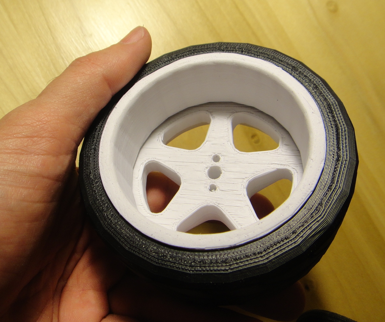
 This photo is of one of the front wheel rim assemblies that is just stacked up at this point to show you what it all looks like without the tire sections in place.  There is a small outer rim then the center five spoked hub and then a larger rear rim.  These three pieces took 3 1/2 hours to print on the Makerbot 3D printer.  


This photo shows about half of the components that I printed today.  The white disks with all of the holes are for the disk brakes that will be in the model. The black disk will be in all three wheel assemblies and are spacers to mount the brake calipers in the wheel assemblies.


This photo shows the before and after sanding detail of the center hubs for the wheels .  Once the wheels have been sanded smooth they look very much like a cast plastic part.  


After a short discussion with my brother this afternoon I started printing the tires for the wheel assemblies so that each half of the tire were a mirror image of one another. (there are two pieces for each tire) so that the tread would be correct with a "V" form running through it.  This was more correct than having both sides of the tire being exactly the same.  Just looks a lot better.  Thanks Denny!


This gives you a good idea of how large these tires/rim assembly really is.  The outer diameter of the tire is 3 3/4 inches.  With the parts being this large it is easy to get some real detail in the electric car model.  The lower photo shows the rim cavity that will be filled with the disk brake, caliper and center hub.  The center hub will mount to a full working suspension and front rack and pinion steering. These parts will also allow for mounting of the front fenders. The assemblies are tight enough when put together that no glue is needed to keep everything in place.  The two tire pieces actually hold the entire assembly together.  
  I finalized the design of the front suspension and the tweaked the rack and pinion also today on the computer model.  Hours at this point in just design is around 70 hours so it will be interesting to see how many hours I will have in this model once I have completed it.  
  The one nice thing about this model over the Semi and trailer assembly I did some time back is that there are fewer parts and they are larger.  It got pretty boring building some of the semi just because there were so many parts that were the same and had to be printed over and over again. (22 wheel assemblies!)  Once I get all the wheels printed I will start printing the front suspension and chassis parts.  Should be interesting and fun at the same time.  I am more than happy with the wheels so far as these assemblies alone are quite impressive with the detail that are in them.  

Tuesday, July 24, 2012

New 1/6th Scale Electric Car Model Project Begins!

This past week I have been burning the midnight oil for several days designing a 1/6th scale electric car model.  The tally so far for the design has exceeded 50 hours. This vehicle or something like it has been on my mind for years and I am happily now making a model with my Makerbot 3D printer.  Printing of the first parts for the model started today and will continue for some time in the future until it is completed.  With that in mind here are a few photos of some of the first parts.


I wanted as much detail in the model that I could make and so have decided to have a full suspension complete with working shock absorbers.  The puzzle to figure out in the design of the shocks was how to hold it all together.  This was accomplished using a small press fit 3/32nd diameter steel pin.  The pin is slid into the upper portion of the shock through the slotted inner lower piece.  This holds the assembly together without the need for glue. With the 3/4 inch long by 1/2 inch diameter spring and the slot in the lower portion of the shock assembly makes the shocks fully functional.  I made the press fit pins by cutting them from a piece of steel rod that I had left over from the Gyrokite project.  I used a carbon fiber disk and my Dremel tool to cut the pins to length while they were held firmly in a table vise. (A two second job for each pin.) 


The first two of four shocks needed I completed today. They are 2 1/4 inches from mounting center to center (uncompressed) and are 1 and 7/8th inches compressed.  I would have completed all four shocks but the hardware store only had a couple of springs that I needed so the other two will have to wait until I can acquire more.   All four shocks took three hours to print on the Makerbot.


Here are a couple of good computer images of the electric car model (without a body).  It is complete in scale right down to the correct electric motor and lithium battery packs. The model as I said earlier will have a working front and rear suspension and also will have a working rack and pinion steering system.  The model will be 24 inches long and 13 inches wide.  Overall height will be 7 3/8ths inches.  Being this size it will be an impressive model comparable to my Makerbot Semi and trailer and allow me to put nice detail in the building of it. I have a wooden figure of a person that will fit exactly into the model.  It (Him? or Her?) stands 12 inches tall and would be six foot tall in real life if and when this model ever becomes a real vehicle some time down the line here at the Tinker's Workshop. 


Monday, July 16, 2012

Gyrokite Project Completed

This past month or so I have been working on the Gyrokite project.  Today I put the finishing touches on it and am happy as usual that it turned out as well as it has with all the tinkering that needed to be done to design and build it.  First off for those of you that have not been following my blog for that amount of time this gyrocopter is a remake of an old design from the 1960's I came across and decided to update and build.  It is a kite so the name Gyrokite was born.  (My idea).  The finished gyro stands 19 3/4 inches tall and has a 19 inch long fuselage.  The dual counter rotating main rotors are 36 inches from tip to tip and the tail structure is 9 1/2 inches across.  


The fuselage is constructed of fiberglass and it has at least fourteen coats of primer on it.  This was primed and wet sanded, primed and wet sanded over an over again before five coats of banner red paint was applied.  As you can see from the photos it was worth the effort to get this kind of finish on the Gyrokite.


 Doing the final assembly of the Gyrokite turned out to be  a comedy of errors.  I had assembled the main rotors and top vane on to the main rotor shaft assembly only to find out that the top rotor hub was assembled upside down.  This caused the top main rotor to tilt down instead of up and collide with the bottom rotor.  Not a good idea at all. Also the top wind vain was completely backward in the assembly.  I had to remove the main steel 3/32nd rotor shaft and had to make a new one to replace it to correct the problems.  This only took about ten minutes or so but at least everything was made right very quickly and it is now ready to fly. 

For more information about the construction of this little beauty go back to the blog here over the past month as I have posted all information about how the Gyrokite was put together from the main rotors to the landing skids.  I will have to get a good windy day to test fly my latest project and hopefully I can get a hand with shooting some video of the maiden flight.  If I can I will post the video here when I do.  My brother who was visiting me over the weekend hopes that it will fly as good as it looks.  I wish for the same but even if it does not turn out like I hope and believe it will this project will in no way be a failure in my eyes if it does not fly well or if at all. (But I am still keeping my fingers crossed for the first flight!) I learned a lot about finishing fiberglass so that I can get a near perfect surface for painting because of this project.  That alone was worth the effort and something that I will carry forward in future fiber glassing projects.  Your never to old to learn new things, especially here at the Tinker's Workshop.