Tuesday, April 16, 2019

Dune Buggy Wind Deflectors Project Part Two

Last week I had made some nice progress with this project and I have been lucky so far again this week with what I have managed to get put together. 


Some changes along the way needed to be done with the design simply because of the hardware that was available for the project that needed to be found and one or two errors on my part also.


Pictured above are the mounts for the right side of the dune buggy wind deflector.  The upper and lower mounts look great but I can not say the same for one of the two inner mounts.  As you can see one has a large hole and the other a small hole.  I had missed this fact while designing the parts in Fusion 360.  Both of the inner parts needed a large hole to accommodate the 10mm bolt the holds these assemblies to the aluminum mounts.  So the upper middle mount needed to be reprinted, and painted in primer again for both sides of the deflector assemblies.  Another five hours of 3D printing not counting the sanding of the parts and priming once again.  


This past week the polycarbonate plastic that I needed for the wind deflectors showed up in the mail. I had contacted my local maker space and thought that it might be possible to have these parts cut out on the laser cutter that they have.  No such luck.  Polycarbonate is not something that should be cut on a laser cutter.  We tried before we found this out as the laser only would make the plastic turn yellow because of the heat along with some other issues that would not make it safe to do so in the first place.  So back to the workshop I set out to cutting the parts on my bandsaw.  

I did have the foresight to buy a new bandsaw blade to do the job and was rewarded with the pieces that you see pictured above. The bandsaw blade had 14 teeth per inch and cut through the polycarbonate like a hot knife through butter.  I took my time with the cutting and was very pleased with the end results.    Also in the photo above you can see the holes for the mounts already drilled.  Another easy task using my drill press. 


Here is one of the wind deflectors set up to have the second set of holes drilled into the polycarbonate plastic.  I took two of  the mounts that will be installed on to the deflector and carefully drilled a 1/4" hole through the mounts as a guide and then into the polycarbonate plastic.  Once I had gotten that far I slid a bolt into each mount so that the next holes that needed to be drilled would match up perfectly with the mount and the first holes drilled.  Not a difficult task. I just had to take my time and not rush the process. 


Once I had the four holes drilled into each of the deflectors my next task was to sand the edges smooth with sand paper.  I started with 120 grit, then on to 400, then 600, and lastly with 800 grit. This made the edges very smooth to the touch and cleared the edges very well.  To finish this part of the project I took a small butane torch and slowly heated up the edges to bring a nice clear finish back to the edges.  Again not a difficult task to do but one that needed to be done slowly so as to not damage the edges in the process.  This final step took less than ten minutes and as you can see the deflectors are ready at this point to be installed. 
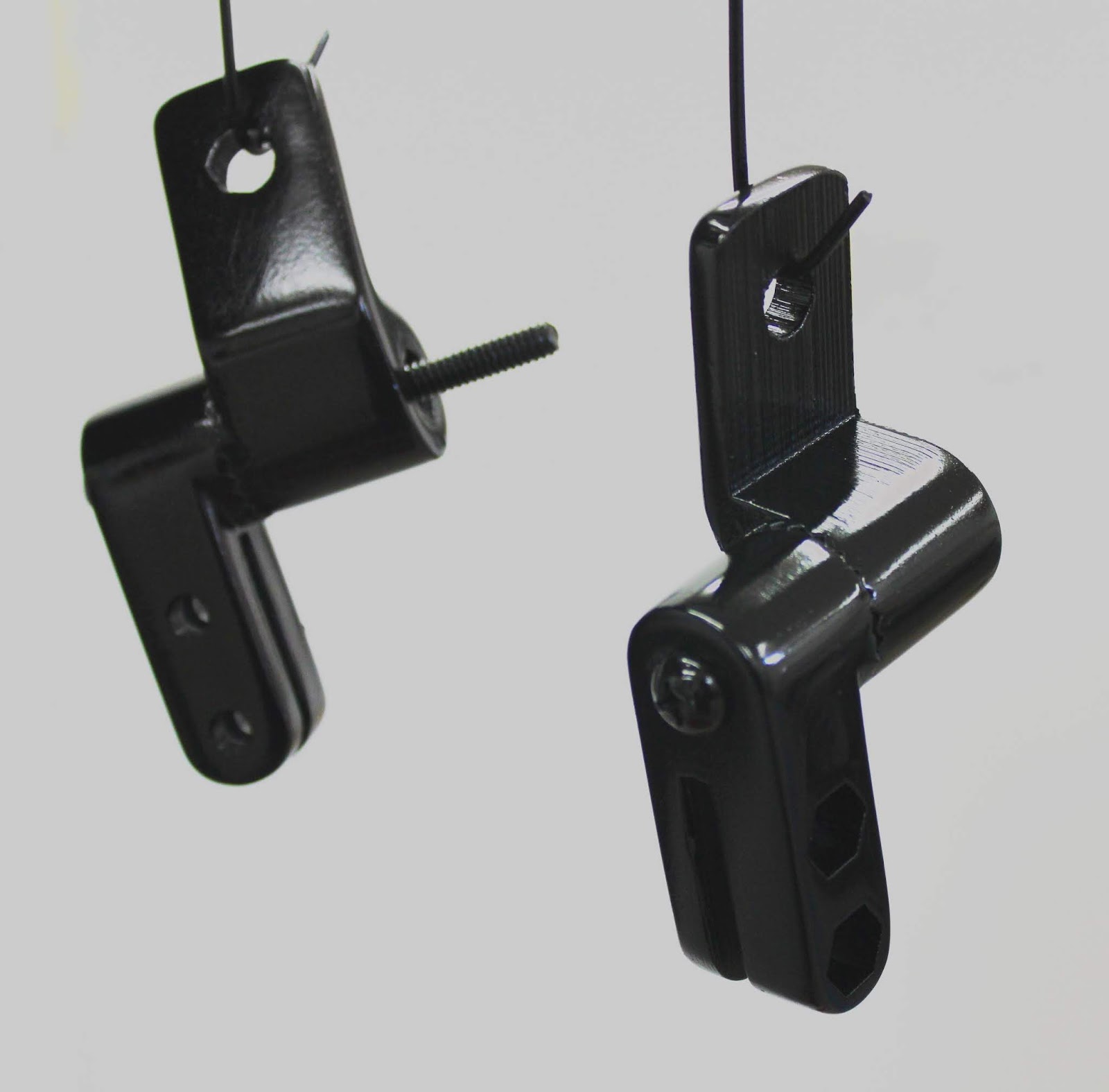


After having 3D printed the mounting hardware for the deflectors I sanded each part smooth and then painted them with primer. When I was happy with how the primer turned out I was able to finally paint the parts a nice gloss black.  I purposely assembled the two mating parts together when I primed and painted them.  I did this so that I could keep paint out of the toothed surfaces on the parts that keep them locked into position when they are mounted on the dune buggy.  I was afraid that if I had painted these surfaces that they would not fit as nicely as what you see here.  


The picture shown above is one of the aluminum mirror mounts that are needed for the wind deflectors. This mounts to the windshield frame first and then the 3D printed parts are mounted to it to hold the wind deflector in place when the assembly is completed.  The 3D printed parts were printed with a 60% infill to make them strong enough for the job.  I think this amount of infill will do really nicely and should hold up very well.  I also think you would have to smack these parts with a hammer to break them so they should do the job.   

The hole in the center of the aluminum mount is a 10mm in diameter with a fine thread.  It took some doing in order to find the right bolt for this portion of the assembly. I needed the right size bolt of course but I also wanted something that fit the look of the windshield and the wind deflectors.  


The bolt on the far left of the assembly in the image above is what I was looking for rather than a large standard bolt head.  This looks good and it took me some time to find it simple because of the size of the bolt (10mm) and it having to be fine thread along with only being 16mm or a little over a half inch long.  I contacted my local Fastenal company and at the moment have the hardware I need on order.  It will be here in a couple of days.  At that point I should be able to start the final assembly of the wind deflectors and install them on to the dune buggy.  Stay tuned for the final part of the build coming up soon. 

Sunday, April 7, 2019

Dune Buggy Wind Deflectors Project Part One

As the work progresses on with my Bugatti model project I also started looking at another project for my dune buggy once again.  As most of you already know I have done a lot of work on the dune buggy to make small improvements to this already outstanding vehicle. I thought I had all the projects done but as usual I spoke to soon.


I have been learning a lot about how a dune buggy drives like even though I have yet to have a chance to drive the one I have down the road due to lack of warm enough weather here in the Midwest.  With my online research I have found that the dune buggy will have a lot of side draft wind when it cruises down the road. Or better know as turbulence because of the flat windshield. To eliminate this side wind deflectors normally are installed to stop this from happening or at least reduce it.

Here is a list of what projects that I have completed or have planned for the dune buggy so far.

1. Create and install license plate mounts on front of car
2. Install of 3D printed housing cover to hide ugly hydraulics between the seats
3. Installation of a lock to the rear deck behind the seats
4. Installation of a GPS mount on the steering column
5. Removal of speakers that were badly placed and not hooked up to anything
6. Created 3D printed housing for a 40 watt wireless Bluetooth speaker mounted in roll cage
7. Created and installed fiber glass glove compartment for dash
8. Installation of a video backup camera with LED lights. (Note...there were no backup lights on car)
9. Install needed of wind deflectors on both sides of the windshield
10. Install needed of removeable vinyl Sombrero top
11. Install needed of correct rear tires to match front tires

So you can see I have been busy over the winter months and still have a ways to go before I am done. With that in mind the wind deflectors are at the top of the list now and so the reason for this posting.

With my research online to find information about wind deflectors I came across several manufacturers of this item.  Prices ran from around $200 on up to as much as $300 or more.  I looked at the different assemblies and how they are installed and once again knew that I could make the assemblies cheaper without having to drill holes into the windshield frame of the dune buggy.


Pictured above is what one of the deflectors look like.  This photo is of a deflector sold by Meyer Manx dune buggies. It was a good place to start as from the site I was told that the holes in the polycarbonate plastic were 14 inches apart.  From this bit of information I was able to create a template of the shape and scale it so the holes would be exactly 14 inches apart.  This would make the rest of the drawing to also be correct.  At least that is what I thought. More on this later.


Here is a good example of a pair of wind deflectors for a dune buggy.  Nice but once again holes would have to be drilled into the windshield frame to mount them.  Not what I want to do.


Again another good set of wind deflectors also needing holes drilled in windshield frame to mount.  Plus the fact that these deflectors cost around $300. Not what I want to spend.


Here is a good looking buggy with the wind deflectors installed.  I think this will be great for my buggy as well but I want to keep the cost down without having to drill into the windshield frame to get them installed.


This gentleman has the same idea that I have by using mirror mounts to hold the wind deflectors in position without having to do any drilling.  I found this photo online.  What you see here is actually part of a glass shelving unit for a bathroom.  Not sure how he managed to get the shelving mount to mate to the mirror mount though.


What I have in mind is to use the aluminum mirror mounts along with 3D printed pivot mounts for the wind deflectors.   The deflectors themselves will be made from 1/4" polycarbonate plastic and the 3D printed parts will have a 60% infill to make them strong enough to do the job.  With all of the 3D printing that I have done over the years I thing that a 60% infill should do the job nicely.  The only way the parts could fail is if as my brother had said was to have a major bird strike the mount or at least hit it with a hammer.

By the way for those of you unfamiliar with the term infill in 3D printing this is the amount of plastic within a part when it is printed. If you 3D printed a cube with nothing inside it would be hollow and have a 0% infill.  If the cube was solid it would have a 100% infill.  So I think 60% should work fine for the mounts.


Here's a good look at how the upper and lower mounts would look.  The mounts are attached to the aluminum mirror mounts so there will be no need to drill into the windshield frame which makes the installation much quicker and easier. 
Here's what the aluminum mirror mounts look like and I will be using to mount the wind deflectors.  I have these mounts on the car now and they are well made and are easy enough to install.  Just a couple of minutes to mount all of them for the deflectors so that is a plus.  That and the fact that a mounting hole is already for use could not make things simpler. 


I have the polycarbonate for the deflectors already ordered for the project.  To mention the shape of the deflectors again I originally had copied the image that I had gotten online from the Meyers Manx site.  I cut out a template and this is what I found out.  The shape I had created was good but it looked way to large to use for the project. You can see in the photo above that the deflector if mounted would extend above the edge of the roof line. Not what I wanted at all. Just does not look right in my eyes.


I went back to my computer and reworked the template for the deflectors by shortening the height by three inches.  Now this looks more proper so that is the plan now to use this template for the project. 

It will take me a couple of days to create the 3D printed parts for the mounts which should not be any big problem.  I have the aluminum mirror mounts ordered and should receive them in the next couple of weeks.  When the polycarbonate for the deflectors also arrives I will see if I can get the parts cut out on a laser cutter at my local maker space. If not I know I  can cut them out using a band saw but then some work will have to be done on the parts to sand the edges smooth and then make the edges clear again by using a butane torch to heat the plastic.  I have played with this process before so I know it will work and not be terribly difficult to do.  Just will have to take my time with the parts to get them the way I want and looking good when I am done. 

That's about it for now on this project.  Once I get the materials together and start making parts I will post more info.  It will be another nice addition to the dune buggy.  By then the weather will have warmed up enough for me to actually get it on the road and test out the deflectors too.  Should be fun to be sure. 


Tuesday, March 26, 2019

1/6th Scale 3D Printed 1927 Bugatti Type 35 Model Project Part 3

I have been plugging along on the Bugatti project again this past week and am happy to report that I have finished 3D printing all of the wheels and hubs for the model.  This was actually a major part of the 3D printing that needed to be done coming in at 95 hours total for the tires and rims.  With that effort I am rewarded with the knowledge that the model will have wheels that will roll instead of being locked in place.


Each tire other than the spare is made up of all of the components you see pictured above.  Starting from the left and moving right you have the outer rim, the tire, inner rim part one, inner rim part two, and finally the brake cover.  I split up the inner rim into two pieces so that I could get nice clean surfaces on both sides.  These parts were glued together after I 3D printing them.  It worked out very well. 


This is how one of the tires looks on the side facing out.  I like the detail I was able to achieve with the bolt pattern on the outer portion of the rim.  The tire itself turned out very well also. 


Here's a shot of the inside of the same tire showing the brake cover.  The little stem on the right side of the brake cover will be the mounting place for a small lever that is used to make the brakes work in the real car. 


I am happy to have this portion of the model completed only if it is just the tires and rims.  It gets kind of boring making the same parts over and over again.  But all of them turned out very well and will look great on the model once it is completed. 


Here is how the chassis looks at this point in Fusion 360.  It has taken me a good part of the week just to finish up the front suspension and work out all of the parts for the rear setup as well.  Starting to look like a real car so that is good. 


The bell housing at the rear of the car will be an interesting part to put together.  Like the tires I plan on 3D print this into two parts.  This way I get nice detail in that part of the assembly with very little clean-up after it has been 3D printed. 


I needed the rear axle assembly in the model so that I could mount the wheels properly. The axle is held in place by two leaf spring that are mounted on to the tail end of the frame and then face forward to meet up with the rear axle.  Along side the frame are also two radius arms that go from the frame reward to the axle on the outside of the body. 

This setup took me some time to figure out how to design so that I could 3D print the parts to make it all work.  Being as the model is only 1/6th scale some of the parts get pretty small to make so I have to do the best I can to make it all work and look as correct as possible. 


 Here's and underside view of the frame setup showing the front and rear axle layouts. I still have more cross braces that need to be mounted between the two main frame rails but as for as I can see this should not be a big issue to work out for the model. 


I do not plan on making the engine for the model as it will not be seen once the model is completed.  I do want to put in a good detailed version of the cockpit though with of course seats, steering wheel, gauges and the like so I will just have make it as complete as I can when I get to that part of the design.  As for the underside where the engine will be at this point I may just close that portion of the model up. I will again just have to see how difficult it would be to have an engine in the model so this may all change.  

I talked with my brother on and off about the model over the past month or so and we both agreed that if the model was say 1/4 scale a lot more detail could be added to it.  This is a given. But I would find it even more difficult to 3D print such a large model being around three feet long.  If I could then I would make it radio controlled so I could at least play with it in my back yard.  But I am not sure that my 3D printer could make such large parts so at this point it is just a passing thought. 


Finally for this post I wanted to mention the Haynes book "Bugatti Type 35 Owner's Workshop Manual" by Chas Parker.  This book has given me a wealth of information about the Bugatti Type 35 along with many photos that I have not seen online.  Also in the book is the history of Mr. Bugatti himself and many of the drivers that raced this amazing vehicle.  It has helped me greatly in being able to model the Bugatti so that I can 3D print it.  I just hope I will be able to do it justice to the car when I am done.  

So that's about all I have for you this week.  I should be able to start printing parts of the chassis and body in the coming weeks so that the model can start being assembled.  Should be interesting to say the least.  

Tuesday, March 19, 2019

1/6th Scale 3D Printed 1927 Bugatti Type 35 Model Project Part 2

This weeks brings a lot of design progress to this project. With the body panels pretty well done along with the front suspension starting to take shape the hours I put into the design are coming together.


Here's a good view of the Fusion 360 model as of this morning. It is starting to look like a proper Bugatti Type 35 so I am happy for that much.  


I have to keep reminding myself that this will be a model and not an actual car that will be assembled like a real car.  The perfect example of this is the front suspension that you see pictured above. In a real car the front axle and leaf springs are assembled separately and then finally together.  For the model it is much simpler to combine these to assemblies into one single part that will be 3D printed.  

I took great care in modeling the leaf springs.  I want them to look like the real thing in the model rather than just a simple representation of the assembly.  This was not an easy task as it took me a little more than a day to get them modeled as you see in the image above. In the model the leaf springs are only around three inches apart so hopefully all the detail that I have modeled hear will not be lost because of the size of the model when I 3D print it. 


In this view you can see the detail again in the leaf spring along with the front brake assembly and the tie rod connections.  The arm on the right side of the brake drum will be connected to a small cable that would pull the arm rearward when the brakes would be applied.  Hopefully I can get the cable installed in the model using a small piece of wire.  That is the plan anyway.


Here's another view of the front end of the Bugatti with most of the suspension installed along with the steering setup.  In the first image in this post you can see a piece of sheet metal that is in front of the radiator.  I left this part off in this image so that you could see the suspension setup easier. 


Among the other features that I needed for the model was the gas cap pictured above.  This image was created using Fusion 360 CAD software.  Looks really close to the real thing in this image. Nice but I only wish that I could make this part as you see it here.  The part in the completed model will be quite small and I will not be able to smooth it out as perfectly as you see here.  That would take an SLA 3D printer and then have to be painted chrome on top of it all.  I will have to settle for my FDM 3D printer and leave it unfinished. 


Here is another good example of what Fusion 360 CAD software can create with this image of the radiator cap and temperature gauge that I designed for my Bugatti model.  Again it would be very difficult to get this as smooth and finished with the 3D printer that I own so I will have to settle for the best that I can do when I complete the model.  


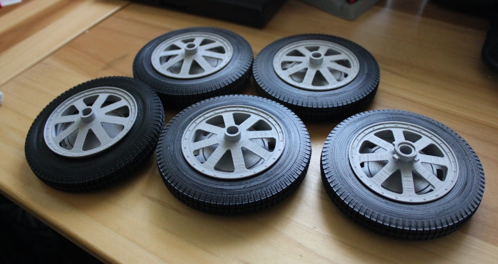
All five of the tires had taken me 43 hours to 3D print. I managed to get some nice detail in the tires by splitting them down the middle, 3D printing them and then gluing them together.  This gave me nice clean tires on both sides and the seam down the middle of the tire is almost invisible so it will look really good once the model is completed.

All in all the model of the Bugatti is coming along nicely.  I have not been keeping track of the hours of work that I have been putting in using Fusion 360 CAD software at this point.  The best guess is that it is in excess of 100 hours already and I know that I have a long ways to go before I can say the design is completed and I can plan on 3D printing all the parts to assemble the model.  A real challenge to be sure.  I'll keep you up to date with further postings on this project. 

Monday, March 11, 2019

1/6th Scale 3D Printed 1927 Bugatti Type 35 Model Project Part 1

This project has been in the works for well over a year.  Or at least it has been on my mind that long and I have finally cracked some of the design issues I had been struggling with creating this model in Fusion 360.


Here is a good photo of the real thing that I got off of a site called Supercars.net.  I created a Blender 3D model of this car back in April of 2015 and I always thought that it would be great to create a good sized real model of it.  I did not want a small model so I decided to make it 1/6th scale. As the real car is twelve feet in length the finished model will end up being two feet long.  I would definitely call that a good sized model.


A key piece that I had issues with in designing a model of the Bugatti was the boat tail rear end of the car.  I struggled with this portion of the car on and off over the past year or more and about a week ago I finally figured out how to get the shape modeled correctly. 

 Pictured above is an image from Fusion 360 of the design.  I will have to 3D print this part with the tail end sticking straight up.  To do this I added an additional brace to the model (shown on the left of the piece) that will be cut away once the part has been 3D printed. 

The best estimate of the time to 3D print this section of the 1/6th scale body will be somewhere around 25 hours.  One of my largest prints ever.  I sure I will be happy when I can hold it in my hands and call it a good part.


In order to get the model to scale and have all of the parts fit up correctly I started out using templates or blueprints of the car which I found online. The top image shows the side, rear and top of the car blueprint. To start modeling the car these images along with the front image of the car are scaled to the correct size and then aligned with each other so they can be modeled correctly.  I need to constantly check several different views to make sure I get every part modeled and lined up correctly.


In the bottom view you can see several of the body parts already modeled along with a couple of the wheels.  This gives you a good idea of how the car will look once all the pieces have been modeled in Fusion 360 so the completed model will look like the real thing when I am done.  Or at least as close as I am able to make it.


Along with the blueprints for the car I gather up a lot of reference photos so that I can get as much detail in the model as I possibly can.  The fact that the model will be two foot long when it is complete will make it possible to get some nice detail in the model much easier than a smaller model.  As you can see from the photos above again of the real cars there are a quite a lot of difference from one side of the car to the other side.


As of this afternoon this is where I am at with the modeling of the Bugatti in Fusion 360.  I am very pleased with how it is all coming together so far.  To give you an idea of the amount of work to create just what you see here take a look at the louvered section of the engine hood. This section has 23 louvers on each side of the hood.

 Each louver needed to be modeled one at a time and takes about 40 commands to create in Fusion.  That is over 900 commands to create just one set of louvers for the hood sides.  I still will need to create even more louvers that go on the top of the hood.  A slow process to be sure but again I want to get as much detail in the model as I possibly can.


I am very confident that the model will work out so I started making the tires. Again I referenced some photos of the Bugatti online and found a good tread pattern that was on a car.  I worked out the pattern and started 3D printing a couple of the five tires that I will need for the model.  The tires had to be split down the center of the tread so that I would have good tread and sidewalls on both sides of the tires.  Once two halves of a tire are 3D printed it is a simple task to glue them together using modeling glue making sure that the tread pattern and two halves are lined up to make it all look correct.  As you can see the tires are a good size coming in at 4.75 inches in diameter and just shy of .75 inches wide.


I have more research work to do on the car in order to create the model but I am happy so far with my progress. I will have to keep track of the hours that it will take to 3D print so that I can let you know how it all tallies up when I am finished putting it all together.  At this point I plan on not sanding the model smooth as I think I would loose a lot of detail in the model by doing so.  Some parts may need to be painted but that will not be a big issue. 

Here once again are images of the Bugatti that I created using Blender 3D.  So far I am liking what is turning out in Fusion 360 as well.  Being as the Fusion 360 model is looking very close to this Blender 3D model that is just a pretty picture and not something that I can 3D print.  

So you can see by comparing the Blender 3D images and the Fusion 360 model images that I am still working on that I have a lot of work ahead of me yet to get the model ready for 3D printing.  Lots of little parts to figure out how to design in Fusion 360 and 3D print. Then also how to put the actual model together once the parts are made.  It will keep me busy for some time yet but so far it looks like it is all possible and should be a lot of fun to create.  In the meantime I hope you enjoy seeing what I have put together so far and have plans for with this project.  I'll post more as I make additional progress.