Wednesday, September 3, 2014

3D Printed Jenny Aircraft Top Wing Starting To Take Shape

With some careful planning and a steady hand I started putting the upper wing of the 3D printed Jenny aircraft model together yesterday and this morning.  I was happy to find that the parts are fitting well together. This is a plus as this portion of the model looked to me to be a real puzzle for sure to make it work.  Here is how it looks so far.


After I had removed all of the pins that held the upper left wing assembly in place it was a simple task of separating the two sections.  The plastic wrap that was covering the cork bulletin board worked perfectly as the parts lifted easily from the surface of the plastic.  Not one piece stuck  to it.  I like it when a plan works out perfectly.  The next part of the assembly called for me to install the two wing struts into these two sub-assemblies. The inner ribs in the two assemblies had not been glued in place as the struts needed to be inserted around the center spar first.


The struts for the wing slide perfectly into place and it was a simple matter of applying modeling glue to the parts to hold it all together.


With the help of a little painters tape the first part of the assembly only needed to be set aside to let the glue dry for a couple of hours.


This outer section of the wing needed just a clothes pin to hold the part in the correct position until it too had dried. 


Once both sub-assemblies of the upper left wing had dried I had to figure out how best to join the two together.  The struts that extend down below the wing actually help solve this problem by supporting the entire assembly.  It was just a matter then of making sure the wing assemblies lined up with each other so the finished assembly would be straight when the glue had been applied and left to dry.  The plus side again in having the assembly work on the bulletin board is that I can move it from room to room if I have to and not disturb anything in the process.  This part of the assembly is a nice start so far and it looks promising to see it starting to take shape so quickly.  I'll let everything dry and will have to repeat the process for the right side of the wing.  A small mid-section of the wing will need to also be assembled but will not be as difficult to make as these assemblies have been.  I'll post more as the top wing gets closer to completion. 

Tuesday, September 2, 2014

3D Printed JN4D Jennny Aircraft Parts, Parts, Parts....etc.

The last few days have been a massive push to print all of the parts for the 3D Jenny aircraft model project.  Total time for this project has been climbing with this push.  Design time was 50 hours and now with the printing of all of the parts for the model this time has doubled to 100 hours and counting.  This is how all of these parts look so far.


This photo gives you a good idea of the scale of a couple of the parts for the plane.  Above the dime in the photo is the frame for the windshield.  The seat with the white cushion turned out perfectly and will look great in the model once it has been completed. The grids that these parts are sitting on are called rafts and are printed on the heated platform of the 3D printer so that the part being made stays where it needs to be while it is being made.  The rafts are removed when the parts are being set up for final assembly.


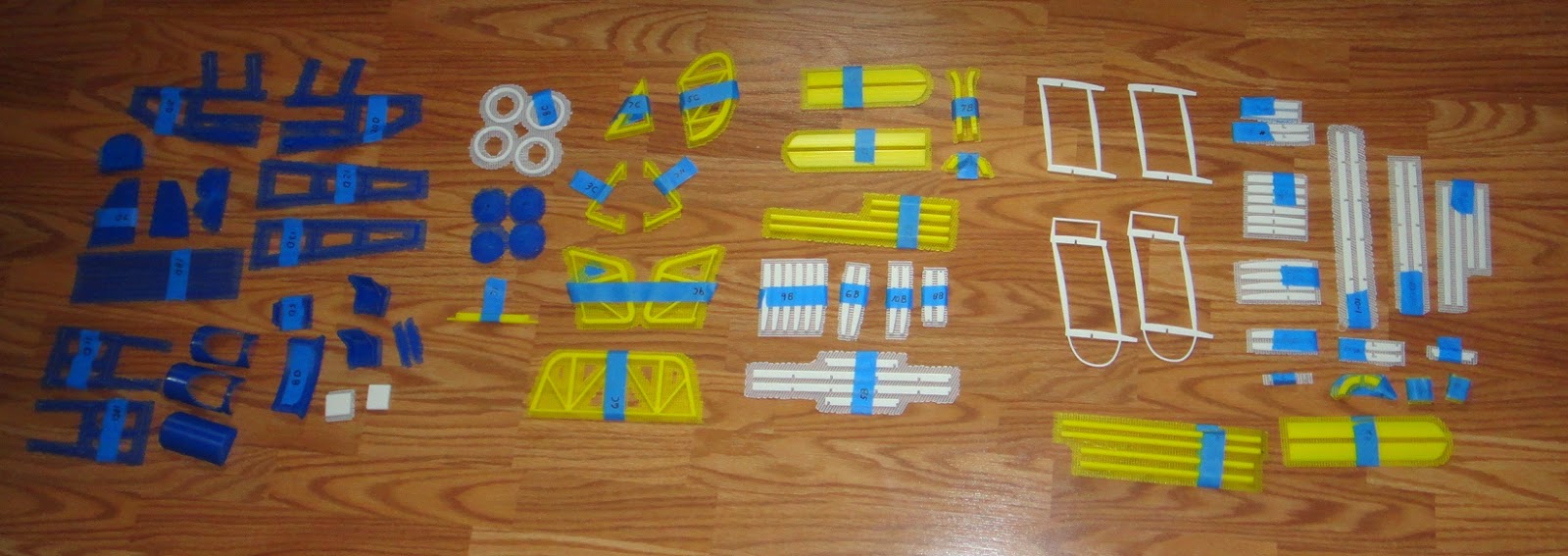
This photo shows almost all of the parts that will be needed for the model.  I shot this photo yesterday only to find out that I had not yet printed the parts for the ailerons and the engine.  So back to printing was the order of the day.  With all of the parts printed the total for the model comes up to 177 parts. No worse than some of the other projects that I've put together over the past few years but still a pile of parts.  So you can see I will have my work cut out for me.


In this photo you can see as before that I have the rafts for the parts still on everything.  I also had to label all of the various parts to keep everything straight for the final assembly.  It will help for sure. 
Each of the parts are laid out for various sub-assemblies such as Top Wing, Bottom Wing, Tail Section, Fuselage..etc.


To start the assembly I pulled  an old bulletin board out of mothballs that I had stuffed away in a closet.  This makes a good working surface to start assembly of the model.  I covered the cork surface of the board with plastic wrap.  This will keep the parts from being glued to the bulletin board and be pinned down to keep every thing lined up properly during assembly.


I used push pins to hold the parts for the upper left wing assembly 'as you can see in the photo above.  I'm sure glad that I have a pile of these pins to do the job.  It will take a while to get everything lined up correctly for each section that needs to be put together. The missing ribs in this section of the wing will be added in the final assembly of the model once the upper and lower wing struts are added to the model and the wings are combined.  Will be a real trick to get it all set up.  Just will have to take my time with it. 


These last two images are what the model will look like once I get it assembled. I originally was going to have the wheels in blue but this had to be changed once I got the parts 3D printed. They did not turn out exactly the way I wanted so I am in the process now of sanding the parts smooth and prepping them for red paint.  I also was going to have the seat in red but decided that the blue and white layout looks a lot nicer.  
  Once I get the model assembled I will look into adding the flying wires that were on the real plane.  This will be a task for sure but will add a lot of detail to the model if I can get it all put together that way.  Again the model will have a three foot wing span and will be almost two feet long.  Should be pretty impressive for sure. I'll post more photos of the project as progress is made with the assembly portion of the Jenny.  Enjoy these photos in the mean time. 


Wednesday, August 27, 2014

Jenny 3D Printed Aircraft Being Dialed In

With 55 hours of design time on the computer model for my planned 3D printed Jenny aircraft I think I finally have the model dialed in to starting construction.  A lot of the sub-assemblies for the aircraft were a real puzzle to figure out how to make. The design for the model had to work and not throw the general shape of the aircraft way out of wack with the effort. So I thought I would show you the progress with this posting about this portion of the project.


The model is looking very complete now with a lot of the littler details added from the first time I posted about the project. In this image you can see the addition of seats, wing king posts and more detailing in the aileron assemblies. With the king posts in the model I plan on adding all of the wires that you would see on a real plane.  These wires criss-crossed at each of the wing struts, up to the king posts and even inside the fuselage between each vertical support.  I will just have to see how difficult it will be to add this level of detail in the model.  Hopefully I can make it all work and give the model that much more realism in the effort. 


The landing gear on the model was quite an effort to design as well for the model.  I wanted to keep the look as close as possible to the real plane and yet not make it a pain in order to assemble or 3D print. The wheels will be printed in four parts each.  This way I will be able to get the white tires and red wheel covers put together easily.  This is simply a matter of printing the parts as though they are halves of a tire split down the center line.  Like a bagel would be cut for breakfast and gluing them together using plastic modeling glue.    


The landing gear is mounted using cylinder and pin mounts that are attached to the upper portions of the assembly.  You can see these mounts (in blue) in the image above just under the fuselage. 


 The axle for the landing gear is shown here in close up with one of the front wheels.  The oblong hollow protrusion on the top of the axle is the receiving mount for the lower portion of the right landing gear.  It took some doing to get all the landing gear parts to line up correctly to make this portion of the model work and look proper. The wheels are glued to the axle with a printed .10 diameter protrusion on the end of the axle.  I will have to make sure that I do some testing of this portion of the axle to make sure that the strength needed is designed into this portion of the assembly.  Would hate to find out that it would fail after I get the model all put together.  


Another brain teaser for the model was the engine and exhaust.  This took a number of hours to figure out how to design using actual photos of a real Jenny Aircraft engine.  The exhaust is pretty close to the real thing so I am happy with my efforts on this portion of the model.  There were several different variations that I found on different planes for the exhaust.  Some had the exhaust tip tipped down, others were straight back to the rear of the plane and still others were tipped up with an extension that would route the exhaust up over the top wing.  I went with the straight back version as it was the simplest to design. 


Here you can see the seats and mounts along with the windshields for the cockpits.  The engine sticking out of the left front cowling looks good in this image as well.  In the model as in the real plane the engine and exhaust stick out of both sides of the aircraft.  I had to mirror the parts for the exhaust in this portion of the assembly to make it look right. 


I started printing some of the pieces of the top wing as you can see from the photo above.  These ribs are only 2.5 inches long and .10 inch thick.  The notches in the spar (the long piece in the photo) match up to the ones in the ribs so there is no guess work when it comes time to assemble the parts of the wing. 


Here is the layout of one of the rib and strut assemblies.  It took me a little while to realize that the simplest thing to do with this portion of the assembly was to combine these parts into one piece for strength, ease of assembly and ease of 3D printing.


Here is the completed 3D print of one of the rib/strut assemblies.  Only two of these parts are needed for the wing assembly and printing one only takes around 30 minutes to complete.  Turned out very well and will make the wing assembly nice and strong when it is mounted into the model.


These two wing/strut parts are different versions of the same part.  The one on the left I printed first.  The upper portion of the top rib is called the king post.  This was used in the real aircraft to attach mounting wires to strengthen the upper wing.  After I had printed two of these parts I realized that the wing skids (the lower loop on the bottom rib) for each of these parts was missing from my model.  So I had to reprint the parts again (the part on the right) to make the model correct.  As before the parts turned out very well and give the model the correct look.  The last rib/strut part is good sized being nearly 7 inches long and 4 inches wide. Will be fun to see the model come together now with the design portion of the project nearing completion. I'll keep you posted once I get enough parts printed and some of the wing assembled.  Enjoy the photos.

Sunday, August 24, 2014

A Project From The Past.... A 3D Printed JN4D Jenny Aircraft

This week at the Tinker's Workshop I have been working on a project that has combined two of my interests at the same time.  One as most of all of you already know is 3D printing and the other is airplanes.  I thought it would be fun to create a model of the famous World War One trainer the JN4D Jenny.  So with this posting I thought I would give you a look at how the project is coming along so far.  The first thing that is called for as is with most of my projects is research on what I plan on making. 


 I started by tracking down some photos of the famous plane that I will recreate using my 3D printer. 


I wanted to make a biplane model and I always liked the look of this famous plane and so the project was born. These photos are a good start but did not give me enough info to layout the computer model to design the model.


I was lucky enough to come across this image online to get me started with this project.  The JN4D plans here were designed to make a balsa wood rubber band flying plane.  I do not have that in mind for this project.  I am going for a larger model completely printed using my 3D printer. (That's the plan anyway). The balsa plans would build a 24 inch wingspan flying model  and my plane will have a 36 inch wingspan and will have more detail in it than would be put into a flying model. So more research was called for. 


I found some photos of a replica Jenny that were taken at the Museum of Flight in Seattle Washington. A beautiful example of a Jenny to say the least.  With this photo and a couple more shown below I was able to get a better idea of how my model should look. 


My model will look very similar to what you see in these photos. (I hope). I do not plan on covering the model with a skin so that all of the internals of the plane can easily be seen and enjoyed. 


Along with my research I have been finding out some interesting facts about the Jenny.  The upper wing is 36 feet long and the lower wing was only 28 feet long.  The plane only cruised around 60-65 mph with a top speed being only 75 mph.  Not surprising with all of the wires and struts causing all of the drag on the plane.  The landing gear for the plane used a tail skid at the rear and the main landing wheels were 26 inches in diameter. It was a primary trainer during WW1 and was supposed to be easy to fly.  Would be fun to take a ride in one that's for sure.


So with the photos and the research I have collected this week, here is how my model looks so far in my computer.  It's starting to look like the real thing anyway and that's a start. 


All that you see in my computer model can be printed using my 3D printer.  The wingspan as I said earlier will be 36 inches and the total length of the model will be around 22 1/2 inches.  This calculates out to 1:14.5 scale. I thought I would either hang it from my ceiling in my computer room either that or on one of the walls.  Will make a nice display in both cases.


I am liking how the detail is coming together in the computer design. I still will have to work out the landing gear, seat mounts, propeller, engine, etc, etc.  So I have a ways to go.  But at least the project looks possible at this point.  I'll keep you posted as I finalize the computer model and start working on printing out parts. 
  I'm not sure about the color for the plane just yet.  What you see here as far as color goes is only set up this way so that I can make sense of all of the parts in the final computer model assembly.  I thought possibly that the planes fuselage would be in red with white wings.  It's and idea anyway.  I'll just have to play around with a couple of ideas before I start making parts. Stay tuned for further developments.

Thursday, August 14, 2014

A Simple Solution To An Annoying Problem

With the completion of the velomobile project my attention has been moved to another large project this time for my home.  One thing that was missing from my house was an entryway from my garage to the inside of the house.  The garage had been added to the house years after it had been built and no stairway was built to get into the house.  This meant that I had to drive my car into the garage and then leave the garage to go into the house even though the garage was attached to the house. Annoying to say the least. Especially during cold snowy winter months when I had to bring groceries in from the car.  Rather than bore you with the construction of the new stairway I found something else within that project that presented another common problem which I found a simple solution for.


With the completion of the new stairway another problem came up.  On one side of the stairway is a window that looks out over my roof top.  This window provides light and fresh air to the stairway but now with the steps installed is impossible to reach the crank to open the window. 


I thought about this for a couple of days and came up with a simple baton that would fit over the top of the window crank and easily allow me to rotate it to open or close the window. 


I went into the workshop and found I had all of the materials that I needed to make the baton other than the 3D printed parts that would make it all work.  The shaft of the baton is nothing more than a two foot length of 1/2 inch aluminum tubing.  This was strong and light enough for the job I needed it to do so I set about designing the end pieces for this simple project. 


At one end of the baton is a 3D printed cylinder with a cavity large enough to easily slide over the window crank.  To hold this piece on to the aluminum tubing I drilled a 3/16" hole in the end  of the tube and fit the cylinder over the shaft.  In the cylinder is a mating hole with a hexagon cavity for the nut and another 3/16 inch hole through the part to mount it to the aluminum shaft. 


The opposite end of the shaft has a small end cap with the same mounting set up as the head of the shaft and makes for a simple nice looking finished end to the baton.  When I am not using this simple tool I lean it into one corner of the stairway where it is out of the way but still handy when I want to use it.  This simple solution cost me all of maybe a dollar to put together but will be a big help in opening a window when I need  fresh air without having to risk life and limb trying to do so.  So now I have a new stairway and still can get fresh air into the space when it is needed.