Thursday, September 12, 2013

TerraTrike Velomobile Framework Is On The Chassis!


I had a few little things to do on the framework of the TerraTrike Velomobile project this morning and I was rewarded for my efforts with the first trial fit up of the framework to the chassis late this afternoon.  I am very pleased with what I see so far in the alignment of the body to the chassis so all is going according to plan with the project so far.


 This is a good shot of the left front of the velomobile.  The double row of foam strip on the top of the body will be where the hood will be separated from the rest of the body.  I will cut between the foam strips so that hopefully I can keep everything lined up nice and straight when I want to remount the hood. 


The alignment of the framework to the chassis is looking very good as you can see from this photo.  I was going to drop the chassis another inch or so but the way it looks right now I feel that this will be unnecessary. It also will give me a little more ground clearance in not lowering the body further. The plus side to seeing just the framework on the chassis is I can see where there may be problems further on in the project.  Case in point is the rear mounts for the body to the chassis.  Once the framework is skinned and glassed it will be difficult to see and reach the rear mounts.  So I might have to look at access panels at the rear of the body that can be removed and reinstalled once the body is in place.  Just will have to take a closer look at that when I get farther along with the project.


I was concerned with the size of the wheel openings but after seeing the alignment and clearance around both wheels I am more than happy with my calculations for the design. I will have to work on some wheel covers to hide what is inside the velomobile while I drive it and also get a little more air flow around the vehicle while it is cruising along. 


This give you a good idea of what it will look like inside the vehicle.  I was also concerned about the front mount of the body to the chassis but at this point I may be able to eliminate it all together.  I think the body will be stiff enough on it's own without additional bracing.  This will eliminate a little weight in the scheme of the things to so it is a double plus in my eyes.  The turning radius for the front wheels looks good too.


The cockpit looks to be plenty roomy.  Sliding the body on to the TerraTrike was a breeze.  Now I will have to bond the mounts to the chassis so that everything is lined up properly when I get the body of the velomobile completed and it will then be a easy task to remount without a hitch.


It's been such a windy day today I did not want to take any chances with shooting photos outside but did get this great shot before I slid the TerraTrike Velomobile back into the garage.  I am very pleased with the look of the project and am looking forward to getting the body skinned with foam strips and then sanded, shaped and glassed before much cooler weather sets in.  I still will have to work on lights and a few other little accessories for the project but that all can happen later.  Until then I will sit back for the moment and catch my breath and smile from ear to ear admiring my handiwork.  I hope you enjoy the photos as much as I am right now.   Have a good day in your workshop too!

Tuesday, September 10, 2013

TerraTrike Velomobile Rear View Mirrors

With the return of the hot weather to the Midwest I have retreated once again to my computer room and other tasks that I needed to accomplish for the TerraTrike Velomobile project.  This in case being rear view mirrors for the vehicle.  I needed these more than I could ever imagine while riding my Terratrike around town and now with the progress being made on the velomobile project I thought it the perfect time to design something that should work well with that in mind.


 I wanted mirrors that were small so that they did not add much wind resistance to the vehicle and so I decided on using the blind spot mirrors that most people have on their cars today. 


The mirrors are the right size at only two inches in diameter.  I worked up the design on my computer and this is approximately where they will be located on the vehicle.  I won't know for sure until I get the body near completion and I can sit in the velomobile and see what I can see with them located where they are now.  So once I was happy with the design I started making the parts for the two assemblies.


Here one of the rear view mirror assemblies has been put together.   The parts were only held together with double stick tape for these photos just so I could show you how it will look. So please disregard the poor alignment of some of the parts. That will be corrected once I permanently bond all the parts together.  I want to do some sanding on the parts also to smooth them out further and then paint the housing (without the mirror of course) so that I can get it to match the velomobile when I am ready to paint the entire body. 


 Here are all the components that make up one of the mirrors.  At the very top of the photo is the outer housing.  The first row below the housing from left to right is the backing plate, mirror outer mounting ring, and then the wide angle mirror.  The bottom row from left to right shows a 1/4 inch threaded rod connector, the mounting post which the threaded rod connector slides into, the bottom mounting plate, and lastly a 1/4 inch by 1 1/2 bolt.  


 The mounting post is made up of the threaded rod connector, the mounting post itself, the bottom mounting plate and the 1/4 inch bolt.  This assembly then will be slid into the cavity that is molded into the bottom of the mirror housing.


The mounting post is then glued into the cavity in the mirror housing.  I really like the look of the mounting post and housing together.  Nice and clean.


This photo shows the last part of the housing assembly other than adding the mirror.  The backing plate (the part in the middle) is glued on to the housing of the mirror assembly and is aligned with the inner block by the indentation shown on the part.  Once this is set then the outer ring is added to the face of the backing plate so that the mirror can be centered on to the assembly. 


This photo gives you a good idea of how small and compact the mirrors for the velomobile are.  The fact that I am using wide angle mirrors instead of flat ones should work out when when I am driving the vehicle.  This plus the mirrors are not that far away from me when I have them mounted.  
  Total time to print all of the parts for the two mirrors added up to 5 1/2 hours.  This brings the total tally on the project so far to around 185 hours.  So the time is adding up but the progress is encouraging.  Lots more to do but that is the fun of it all.  
  Once the weather here cools off a bit more I will be able to get back to the building of the body of the velomobile.  In the mean time I am also looking at setting up turn signals for the project.  Hopefully that will all fall into place soon also.  Just will have to see what I can figure out to make that part of the project come together too.  Enjoy the photos and have a good day tinkering!

Friday, September 6, 2013

TerraTrike Velomobile Comes Off The Jig

Progress is moving right along on the TerraTrike Velomobile project with the body being removed from the building jig today.  Higher temperatures have also returned to the Midwest and the garage where the project is being built and so work has to be done early so that I do not melt in the process.
   Yesterday I was doing some fiber glassing and it got so hot that the resin I had mixed for the project cured VERY quickly in the mixing cup. Not a good thing to happen. So I set that part of the project aside and went to work on the mounts for the body in the much cooler workshop.  Here is what I managed to get done. 


 One of the smaller group of assemblies that needed to be built for the Velomobile project was the hard mounts for the mounting of the body to the Terratrike frame.  I started with a 1 x 2 inch piece of wood.  On this piece of wood I marked out six hard mounts that the hardware to mount the body will be attached to.  On each marked out mounts I drilled two 1/2 inch holes.                             


 Here is one of the mounts with the bolts and threaded rod connectors being mounted to it.

 In this photo you can see all of the mounts that will be assembled in this step of the project.  To hold the threaded rod connectors into place a small amount of fiber glass resin and micro-balloon mixture is poured into each hole first. Then the mounts are inserted into their corresponding holes.


 The bottom of the threaded rod connectors are taped off as these will be inserted into the holes of the hard mounts and I don't want epoxy resin to get into the threaded holes.


The bottom of the yellow mounts are covered with plastic wrap to protect the mount from being glued  to the wooden mounting board if to much resin should spill out of the mounting holes during the set up of these assemblies.  The yellow mounts help keep the threaded rod connectors in alignment while the resign hardens.  


After the resin had cured over night I removed the yellow mounts and what is now left is the threaded rod connectors that are imbedded into the wood and encased in fiber glass resin.  This makes a perfectly aligned threaded insert for the mounts and they will attach perfectly every time to the hard mounts.


 Next I fiber glassed the top surface of the strip of wood, let it cure over night and then cut each mount to the correct length.  I then removed the fiber glass that had covered up the holes by using a utility knife.  This left me with six perfectly made hard mounts for the project.


 Here the yellow mounts are once again attached to the newly cut out hard mounts.  With the threaded rod connectors already lined up the process of attaching the yellow mounts was a snap.


Here is a shot of the hard mounts attached to the completed body mounts.  The hard mounts will be imbedded into panels in the body assembly.  Once these have been mounted the body can be removed from the TerraTrike  and the outer skin be applied to the framework of the body.


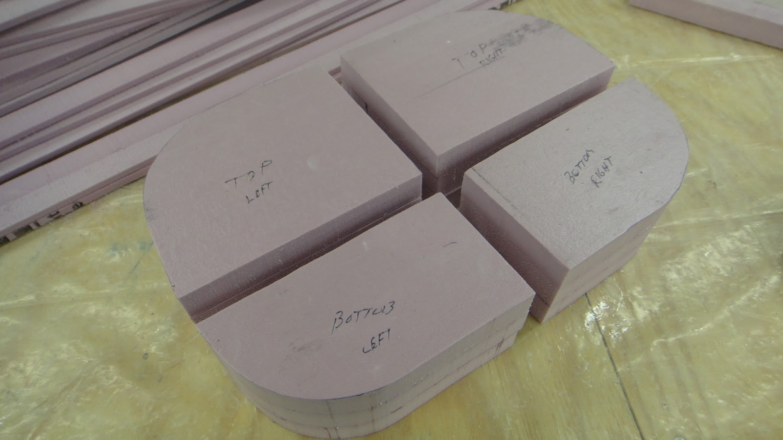
 Another sub-assembly that I completed in the cooler workshop was the solid foam nose section for the velomobile.  I traced out the shapes I needed off of the framework and started cutting the parts out using the band saw.

 Here all of the parts are cut out and ready for shaping.

 I took a large amount of the foam off of the blanks using a hot wire tool to get them into the rough shape that I was going for.


 This is a good shot of one part of the nose cut into rough shape and the other after it had been sanded into shape for the front of the velomobile.


 Here the top section of the nose of the velomobile is placed into position to check that the shape is correct.  Looks pretty good at this point. 


The next step of the project needed to have the opening cut into the framework for the cockpit of the velomobile.  This then was blocked out using one inch foam strips between the ribs and a 1/4 inch foam strip that ran along the inside of the ribs.


 Here the cockpit has been shaped and glassed.  With the upper cockpit glassed it now is strong enough to be moved around easily without the chance of it breaking. 

 I was able to remove the velomobile body off of the building jig today.  This took a little bit of doing as I was alone at the time.  With a little bit of wiggling I was able to remove the framework that you see here.  It was still a bit fragile at this point as the top brace that you see in the photo still needed to be mounted.  Without this brace the front nose of the body had very little support and a couple of the side stringers could have broken.  I installed the top brace and added additional fiberglass to the weak points just above the wheel openings.  I was just barely able to do the work on the framework at this point today as the garage was heating up again.


 Here are a couple of good shots of the Terratrike next to the velomobile body framework.  With the framework off of the jig it looks a lot smaller.  I will have to put the framework up on supports and flip it upside down so that I can complete the work on the bottom of the framework so it can be mounted on the TerraTrike. Once all of this is done then the framework can be skinned with foam strips and glassed.  This will make the entire structure much stronger and I can move on from there to get the project completed.


75,000 Visitors! Let The Celebration Begin! Thank You Everyone!

  With an amazing number of visitors to the site reaching an unprecedented 75,000 today, the Tinker's Workshop has reached a great landmark. 
  I wish to thank all of you who have followed my creative efforts while working on 3D and 2D artwork, tinkering, planning, and building a wide variety of projects over the past two years.  The emails and comments that I have received from around the world have always made my days and shown me that there is great interest in what I am working on, writing about and showing everyone from week to week.  
  It is amazing to me that there is so much interest in what I do and what I still plan on working on in the future.  Because of all of you I am encouraged to continue my efforts here at the Tinker's Workshop.
  So with that in mind again I say "Thank You" and as usual wish that all of you have a great day tinkering in your own workshops. 

Sincerely,

Dave Langkamp
The Tinker's Workshop

Sunday, September 1, 2013

TerraTrike Velomobile Glued, Trimmed And Shaping Up Nicely

  The weather here at the Tinker's Workshop finally cooled down enough today to get some work done on the TerraTrike Velomobile project in the garage.  The work that I completed today does not look like I accomplished much but it is a good step toward on the project.  I double checked all of the ribs and stringers and hot glued them all together. This being only a temporary solution to hold everything together until I am ready to fiber glass all of the joints for a more permanent assembly of the parts.


 With the simple step of hot gluing all of the parts together the structure already is started to be much more solid as a light weight assembly.  


 I only had a couple of joints that needed tender loving care to persuade into position but all looks good at this point.  


With the addition of the upper lip of the front wheel cavities the structure is already looking much more complete. 


In this shot you can see the protruding edge of one of the horizontal stringers before I trimmed it down to the correct shape using a hot wire tool.  This over sized stringer like all the other stringers in the assembly was purposely made this way so that all the individual parts that would end up between each rib could be aligned correctly in the assembly. 


The stringers were fiber glassed and left to cure overnight.  Then the excess fiber glass was trimmed and removed from each stringer.  This left a bare foam section that was removed on the final assembly that I did today. The hot wire tool then was able to cut the excess Styrofoam away and not remove the remaining fiber glassed foam that was left behind between the ribs. A nice clean effective way to get the structure the way I wanted it.


I also cut over 100 of the 1/4 inch eight foot long Styrofoam strips that I will use to skin the velomobile once I have all of the joints fiber glassed together and some miscellaneous parts added to the assembly.  To make the foam strips I first cut up a 4 x 8 foot panel of Styrofoam into pieces 9 - 10 inches wide by eight feet long.  Then set up the band saw so that I could pass these smaller panels through to cut the 1/4 inch strips.  Much easier to work with the smaller panels than trying to cut a 4 x 8 foot panel into strips by itself.  Just to awkward to handle the large panel alone. 
  Hopefully tomorrow I will get the velomobile framework joints puttied and glassed so that the inner panels for the mounts can be added next.  These are nothing more than small glassed Styrofoam panels that are fitted between two of the front and rear ribs so the body can be mounted to the TerraTrike itself.  Again this will make more sense once I get that far with the assembly to show you more detail in the process.  After that is completed then the foam strips can be added to the assembly to skin the framework like a cedar strip canoe.  Hope you are having a good holiday weekend.  Mine is already shaping up nicely.