Sunday, November 20, 2016

Work Table Spray Booth Project Pt. 2

This week brings great progress on my work table spray booth project.  Everything from more 3D printing of exhaust parts to construction of the enclosure itself.  So let's get to it.
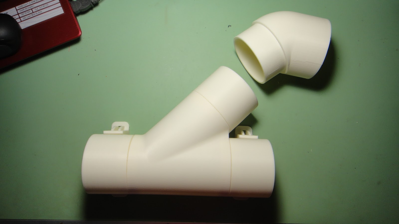

This photo is of all of the 3D printed parts that will be used in the exhaust system of the spray booth. The large part at the center of the photo is a "Y" connector and slid into it are extensions for the flexible hose that will connect to the two exhaust fans.  All of the parts have an outer diameter of three inches.  Just the "Y" part without the smaller extension took 8 1/2 hours to print.  But it like all of the other parts simply cannot be bought.  Cost to make the parts were around $8.00. 


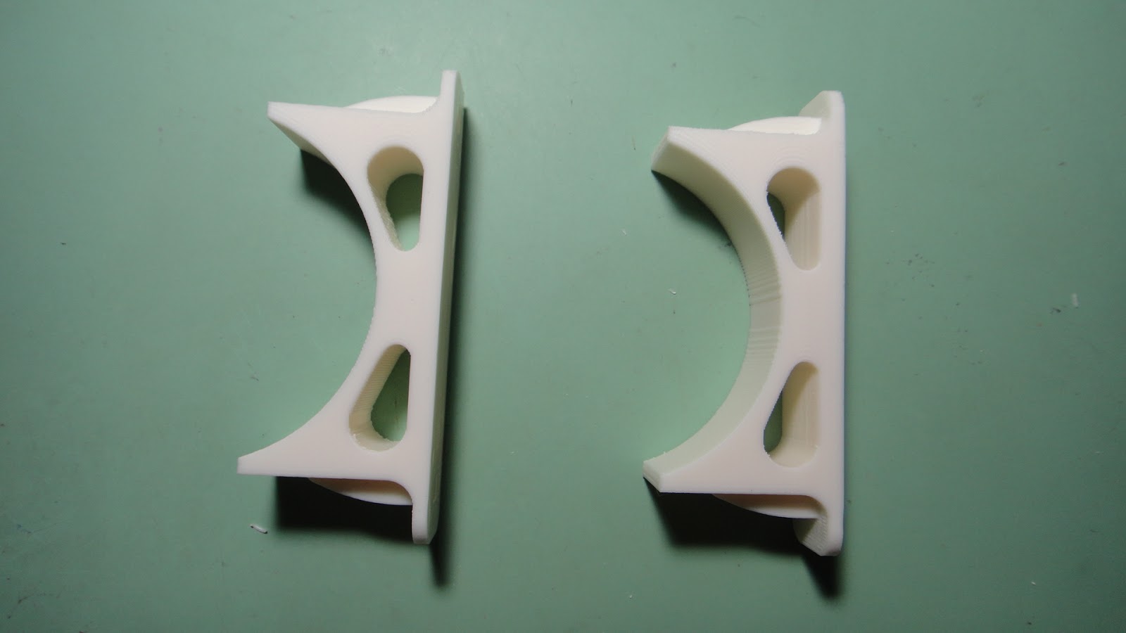
The top photo above is the same "Y" connector with the extensions along with the mounting parts that you see in the lower photo.  The "Y" connector and it's parts will be tied together to the lower mounts using zip ties.  The zip ties that will be fed through holes in the back of the spray booth and should stay in place rather nicely.  Simple is always a good thing.  So with that sorted out I started working on the construction of the spray booth itself.


The photos above are mountings of the framework for the spray booth that surround and hold the furnace filter in place.  I stacked and glued two pieces of 1/2" plywood on two side of a 2 X 2.  I needed two complete assemblies that were exactly 1" square.  I didn't have any wood that I could cut down to that size so I used what I had on hand.  Doing it this way was a bit more work but I still managed to get what I needed and the parts end up inside of the spray booth and will not be seen once the booth is completed so it really didn't matter how they looked as long as they did the job.


I then attached a three inch wide strip of 1/2" plywood to one side of these first assemblies.  This strip of wood is the guide for the furnace filter so that it can easily be installed into the spray booth.


I next took the two small assemblies and attached them to the front filter face that was cut out of 1/2" plywood (top photo).  The middle photo is another small assembly that was used in this portion of the build.  It is simply two pieces of 1/2" plywood 2" wide and 25" long glued together.  They are used in the final assembly to center the furnace filter vertically with the front filter face opening. The lower photo is the backside of the assembly with the furnace filter installed into the assembly.


Next after carefully checking my computer model dimensions of the assembly I positioned the filter frame assembly on to the base of the spray booth which again was made using 1/2" plywood.  I clamped the assemblies together.....checked and rechecked that I had it all in the right place and then screwed the base to the filter frame assembly.


With the filter frame assembly nice and secure I mounted the sides and top of the spray booth.  I made sure that the slot for the furnace filter matched up with the top plywood  part slot.  I again clamped everything in place and then screwed it all together using fine thread #6 -1 1/4" drywall screws.  At this point things were coming together nicely as you can see from the photo above.


I then got to work on the turn table that will be used in the booth.  As with the rest of the assembly I used 1/2" plywood to cut out a nice 18" diameter circle.  I had marked center lines on the square part before cutting it to get my holes lined up for assembly of the bearing plate that will make the turn table work.


Here is the bearing plate along with the mounting holes set up for it.  The bearing plate will be screwed to the circular 1/2" wooden piece and then in turn it will then be screwed to the inside top surface of the base of the spray booth.  The larger holes in the photo are there so that the turn table can be rotated to allow the lower screws to mount to the spray booth base. 


I figured right with the size of the turn table as you can see in the photo above.  The turn table is 18" in diameter and the inside of the spray booth is 20" x 29" in size.  I thought this might be to large but from the looks of it..... it will be a nice sized area to spray parts in.


Back to completing the spray booth construction I assembled the mount for the upper exhaust fan.  It was simpler to assemble the little shelf while the back of the spray booth was not mounted to the rest of the assembly.


I was really happy that I had more than enough clamps to get the last large piece of the spray booth held in place.  There is no such thing in a workshop as to having to many clamps.   Before I started clamping this last part in place I was not sure I had worked everything out correctly.  Once I clamped it all down I breathed a sigh of relief as the fit-up was near perfection.  Nice to see for sure.


With the back of the spray booth in place the fit looks great.  The smaller box on the lower portion of the back is the mount where the electrical switch will be located for the booth.  Again I put this little box together before mounting it to the main assembly.  Made things a lot simpler.


Now with all of the wood construction completed I was able to get this shot of the two exhaust fans that will do the work of moving the air while I am using the spray booth.


The wiring as you can see will be fed into the lower switch box and then wiring will come out of the box and be used to plug into a wall socket.  A nice clean installation.


This is how the entire exhaust system will look once I get it all wired and hooked up to exhaust hoses. But that will come in the next installment of this project.  I more than likely will paint the spray booth rather than varnish it as shown in the photo above.  This will make is simpler down the line if I should ever want to spruce up the spray booth after a couple of years of use.   So that's it for today.  I'll keep plugging along on this project and I should have it wrapped up in the next posting.  Have a good one.

Thursday, November 10, 2016

Work Table Spray Booth Project

With my last post I talked about a custom designed cooler for the trunk of my Goldwing motorcycle that I am working on.  I realized early on with that project that I want to paint it once I have the fiber glassing work completed.  So this project was born out of that need to paint something during the colder months of the year and when I have a project small enough to do so in my shop without creating a mess or a hazard to my health. 
  I did some research once again online and found all kinds of designs for a small spray booth or box that would sit on my work table when the need called for it.  I wanted it large enough to handle a good size project or part but not so large that it would be a pain to pick it up and move it out of the shop when it was not in use.  So with some refinement and design work on my computer this is what I am also working on at the same time the motorcycle cooler project is underway.


My design is nothing fancy but does have some nice features.  The inside dimension of the booth are 20" high, 20" deep, and 29" wide using 1/2 thick plywood. On the base of the booth is a 16" turntable that is used so that any part can be rotated while painting it.  This was easily created using a 6" Lazy Susan bearing that I picked up at my local home and builders store.  This is attached to the inside base of the booth and then a 16" diameter 1/2" thick diameter piece of plywood is attached to the bearing.  Simple and easy to set up.
At the very top of the booth you can also see the Plexi-glass window that will allow additional light into the spray booth without the need for more lights and added cost.


In the back of the spray booth is a 20"x 25" furnace filter which will do the job nicely of cleaning up the air that the booth will extract while in use.  This filter is simple dropped into place from the top of the booth. With the filter removed as shown in the photo above you can easily see the two 50 cfm (cubic feet per minute) bathroom fans that will exhaust the air while painting. The filter will slow the air down a bit but should give more than enough airflow for the booth.


Here a good shot of the rear of the booth that I put together in the computer.  The white tubing in the view is flexible vinyl duct hose that is used with bathroom exhaust fans.  This is connected to various 3D printed elbows and joints that tie both exhaust fans into one exhaust hose which will be routed to a window and to the outside.


Here's a better look at the 3D printed parts that will be needed for the project.  The red elbow on the top exhaust fan is a 3" diameter 45 degree elbow.  The yellow pieces are 3" connectors for the white flexible hose and the green piece is a 3" 2 into 1 fitting.  The only reason that the yellow connectors are separate from the green fitting is that if all the parts were printed as one piece it would never fit into my 3D printer.


Here is what I have printed so far and it gives you a better look at what the real pieces look like.  The elbow at the upper left corner is the 45 degree elbow I spoke of earlier.  The other two cylinders are what will be connected to the 2 into 1 fitting.  The other various pieces in front of these connectors are the support tabs that will be used to hold the Plexi-glass window in place on the top of the spay booth.  I will need to add an electrical on/off switch to the paint booth yet and this I plan to mount on the rear of the booth.  The switch will allow me to turn off the fans when the both is not being used but still leave it plugged in while on the worktable.  

I still have a few more supplies to get into the shop before I can start construction of the booth but just getting some of the 3D printing out of the way will be a good thing to accomplish.  The 3D printed parts above took 14 hours to make.  I figure to get all of the parts made the number of hours will climb to around 27 hours of print time.  But where else would you ever find custom made fittings like these that didn't cost a small fortune. I'll post more about this project once I get into more assembly along with progress on the custom cooler for my bike too. Stay tuned for further details in the coming weeks.  Have a good day on your current project too!


Monday, October 24, 2016

Paracord Binoculars Neck Strap Project

This past weekend I took a long cruise on my motorcycle and ended up in La Crosse, Wisconsin which is around 100 miles from my home. The purpose of the drive was to get a few more miles on my bike since the weather was good and also to see one of my favorite scenic spots in La Crosse called Grandads Bluff.  This is a small park that sits on top of a high peak which overlooks the city.  It is quite spectacular to see and if you every get to La Crosse it is worth the time to check it out. 
  I had the forethought to remember my binoculars and so I pulled them out of my closet and opened the case they were in only to find that the neck strap for them was missing.  I looked all over my house for the strap and simple gave up on finding them.  Probably they were lost when I moved to my home a few years ago.  So to put it simply I used the binoculars without the neck strap which worked out ok and set this project in motion today to make what I needed for next time.


I did a little research online to figure out how to make the binocular neck strap using parachute cord  or paracord as it is mainly called.  I had some of this cord in one of my drawers next to my work table so I knew what the stuff was and where to get more.  After searching online for a little while I found what I was looking for in how to make a nice looking strap.  I just needed a few little items and a small jig to get started with this rather simple project.  The picture above is of just a small scrap of wood with another small block glued to both ends if it.  Sitting next to this little jig are two metal flag clips.


The flag clips are held in place using P-clamps on both ends of the jig.  I figured out that the total length of the neck strap for the binoculars needed to be 24 inches long.  The jig was 32 inches long and with the flag clips on both ends of the jig I would get the length I was looking for.


Here's what the jig looked like once both flag clip were mounted on to the P-clamps. The eyelet on the ends of the P-clamps were where I needed to tie the paracord to.


On one end of the jig I looped the paracord through the end ring of the flag clip as shown in the photo above.  You can also see that the paracord is blue as well as black in color.  I took the two colored cords and pushed them together and then put a lighter to them to join them.  This fused the two lines together.  It will make more sense why I did this as you follow along in this post.


On the opposite end of the paracord jig I looped and tied one end of the blue cord as shown above to the ring end of the other flag clip.  Then I did the same for the black end of the paracord as you can see in the last photo above.


Now the looping or weaving of the paracord to actually make the neck strap begins.  I turned the jig around to make it simpler for me to shoot this next sequence of photos.


The first step was to take the outer black cord and come over the inner black cord then slide it under the blue cord.  Simple and easy as are the following steps.


Next take the outer blue cord and go over the inner blue cord and the first black cord then underneath the outer black cord.


Then continue with the blue cord from the last step and go over the out black cord and then again under the blue cord just as I did with the first black cord.  Then you start again with the black cord as I did in the first step.  The easiest way I could remember this process was to think to move the left most outer cord over two cords, under the right most outer cord, around the right most outer cord and then under the inner cord once again.  Repeat, repeat, repeat.


Here's what it looked like after I had done these steps over and over again about eight times or so.  I had to keep everything as tight as I possibly could and had figured out the starting length of the paracord that was needed before I started weaving it together.  For a two foot strap I need two pieces of paracord nine feet long.  Luckily paracord is pretty inexpensive.  $3.50 for fifty feet.  I had the black already I just needed the blue to give it a good look.


Once I had finished weaving the strap and had come to the opposite end where the flag clip was at I had to finish it out.  I tied a half knot at the end to hold the two ends of the paracord in place for starters.


To finish things off I took a paper clip and fed one end of the black paracord through it like a needle.  With this then I used the paperclip to slide under four or five loops that had been already tied to feed the end under them to keep everything nice and tight and neat looking.


Here's another look at the process.  It looks a bit messy in this shot but you'll have to see how it all turned out in the next photos.

In order to get the new neck strap attached to the binoculars I simply attached two key rings to the mounts that were already on it.  The flag clips would then be able to be attached or detached from these rings when needed.


Here's the end result.  A rather spiffy looking neck strap  that clips on to my binoculars. I like the black and blue color scheme and the fact that the strap is just the right length and is comfortable around my neck.  Also the strap is very strong and should hold up well for years to come. It even fits into the carrying case the binoculars are stored in!  A win-win in my book for sure.  The strap could also be used for a DSLR camera too.  Something I will have to make again when I do spring for new photo equipment some time in the future. For now this will be an excellent replacement for the original strap that has gone missing.  


Friday, October 21, 2016

Honda Goldwing Micro Cooler Project

Only having had my Goldwing motorcycle a few weeks now already I am making plans for next summer when the weather is a lot hotter than it's been here for the past month or more.  Not that I am complaining about the fall weather we've been enjoying here in the Midwest.  Nice to see another season come before old man winter sets in.  But I digress a bit here.  Anyway to the point of this post. 

With my last motorcycle I had designed and built a custom cargo trailer for that bike.  Not so sure I want to go to that extreme again with this Goldwing so I thought I would go with something a lot simpler.  I really liked the capability of having a cooler along on either a day trip or even much longer journey.  So with this in mind I decided to design and build a custom cooler for the trunk of my bike.


The goal with this project was to design and build a simple little micro cooler that would fit into the trunk space of my Goldwing. I liked the idea of just being able to carry a few bottles of water and maybe a sandwich or two in the cooler and still have room for my helmet and a few other necessities in the trunk at the same time. I looked at using my smallest Igloo cooler I own which would have fit by itself but not with the helmet along with it.  So I came up with this odd looking shape that you see in the photo above.


I then played around with several different combinations of drinks that I could easily fit into the cooler and also allow for ice that will be needed to keep things nice and cool on the road.  The water bottles are 16 oz. and the cans of pop are 12 oz. so it gives me a good variety that can be hauled in the micro cooler.


To build the cooler I started out with standard 1" Styrofoam.  The same stuff that you find at any home and builders store. I had to work out the shape of the cooler to fit into the Goldwing trunk which took a little doing but was not terribly difficult. 


I then hot glued the lower portions of the cooler parts together and got a general shape that I thought would do the job and fit into the space that was available in the bike. At this point I was just doing some testing to see if this idea was even possible.


After putting the micro cooler into the trunk I then tried to put my helmet in as well. As you can see it looks good at this point but I was not happy how close everything was when trying to put the helmet in.  I wanted it to drop in without having to fuss with it even just a little bit so I had to make a few adjustments to the cooler to get it to where I wanted it to be.


I figured out that I only needed about a half inch more clearance to get the cooler to where I wanted it to be but I did not want to loose any volume in the process.  I looked closely at the interior of the trunk of the Goldwing and on the right hand interior there was a little step that ran along the floor of the trunk as well as another extrusion that ran vertically up the back.  The trunk also is nowhere near square at all so the little cooler needed to be kind of an odd shape to fit into the space. I trimmed the outer right face of the cooler to fit the extrusions in the trunk and this gave me an additional 1/2 inch to move the cooler more to the right of the trunk and in turn make it easier to put my helmet into the space that was available.


The back of the cooler also needed to be tipped 25 degrees toward the front and even the front face is angled to match the interior shape of the trunk.  An irregular shape to say the least. But even with this odd shape I still managed to obtain a nice volume for what I wanted to carry when I am traveling.


Next I needed to work out the lid for the micro cooler.  This again was a simple task of just tracing out the outer shape of the body of the cooler and then cutting it out using my band saw.  For the inner plug that would drop into the cooler body another piece of one inch Styrofoam that is an inch smaller all the way around was added to the first part of the lid and then hot glued into place. 


The final step in this portion of the project was to simply sand all of the edges of the container to get a nice rounded shape so that I can get it ready for fiber glassing.  This I will start working on in the next week or so as I have the hinges for the lid on order from McMaster Carr and they should be here in short order. To give you a better idea of how the cooler will look once it is completed here are a few images of it that I created in Fusion 360 when I was doing design work on this project.


I was going to have the decal made for the micro cooler but after finding out that it would cost $8.00 just for one label I scrapped that idea.  The only parts that I needed for the project so far was the hinges and they were only $6.00.  Everything else I needed I had laying around in the shop so my cost is very little at this point.  I would like to keep it that way.  I'll post more about the micro cooler when I get it all put together and do some testing on it on how well it keeps things cold.  I think it will do really well considering that it is all Styrofoam and is one of the simplest projects that I have taken on it a very long time.  It should come in handy next summer when I am doing some touring on the Goldwing.
  The dimensions of the micro cooler are 10" wide, 8" high, and 10" to 13" deep depending on what side you are measuring.  The depth difference is because of the front angle of the cooler that roughly matches the shape of the Goldwing trunk space on the right side.  No matter the shape I am looking forward to having this little cooler along with me next summer when I cruise down the road. 
  Stay tuned for more info on this project!