Tuesday, November 19, 2013

TerraTrike Velomobile Electrical Parts, Body Work and Wheel Covers

The last week or more has been kind of crazy here at the Tinker's workshop with all that I have been working on.  So I thought it best to try and get caught up on my posts here and let everyone know what I have been up to.  So here goes.
  The first order of business has been the continuing work on the signal light housings for the velomobile.  Just yesterday I received in the mail the LED's that I had been wanting for the  housings in the vehicle.  I wanted to be able to see if the signal lights were on when I am riding in the vehicle.  Without an indicator light it would be impossible to know for sure.  So this is what had to be worked on first. 


I was able to mount three LED lights into the panels for the signal lights.  You can see them just ahead of the toggle switch.  The two larger openings in the panel will be where the wiring will be fed into and out of the control panel for the signal lights in the body of the velomobile. 


Here the lights are turned on and to say they are bright is an understatement to say the least.  This will be really good in bright sunlight as well as at night as it should light up the interior of the velomobile while the lights are running.


This is what the signal light control panel will look like once it is mounted in the black enclosure. Should look really good once I get that far in the construction.  


The next portion of the velomobile project has been the continuing work on shaping and smoothing out the body for the final fiber glassing that will be done on the outside skin.   As you can see from this photo the rear of the velomobile is getting a bit smoother with the additional resin micr-balloon mixture (white putty) that you see here.  The shape is coming right along and I am more than happy it is turning out as well as it is. 


Another good view of the rear on the opposite side of the velomobile.  I will be happy when I can finally fiber glass it all as at this point the styrofoam is still quite fragile.  It can be dented very easily.


In this picture I have been working on the fit and finish of the front hood.  I wrapped the body of the velomobile with Handiwrap plastic to keep the putty mixture from sticking to it.  I then was able to fill any voids between the hood and the opening with the resin micro-balloon putty mixture and let it dry. 


Another view of one of the front seams of the hood and body of the velomobile. 


Once the putty mixture had dried all I needed to do was remove the plastic wrap and lightly sand the top surface of the hood.  This gave me a nice straight edge that will match up nicely with the body. 


This is what the hood looks like once it is closed.  A perfect fit.   Once I get the hood all dialed in then I can turn my attention to the rest of the body. 


In this shot you can see that the hood still needs a little work but is coming along nicely with the edges lining up pretty well. 


Continuing on now was the first attempt at making fiber glass wheel covers for the velomobile.  I started with a couple of layers of one inch styrofoam glued together to get the right thickness that I needed for the male blank for the wheel covers.   I weighted the panels down with a couple of full paint cans and let the panels dry over night.


I then marked the center of the new two inch thick panel and cut a one inch hole in the middle of it using the hot wire tool you  see below.


This tool comes from a company called The Hotwire Foam Factory.  and I have used it extensively with all of the foam and fiber glassing projects that I have built over the years.  A great tool that you plug into power and it heats up the steel rod.  I then only have to plunge it into the foam and follow my circle that I drew. It is cut out in less than a minute with very little mess.  A great tool for this kind of work.


 I next added an attachment to my hot wire table for the blank that I just completed.  This attachment is nothing more than a piece of wood that I can adjust on the table with a vertical wooden dowel to receive the foam blank for rotating.


With the blank placed on the vertical wooden dowel all I needed to do is move it into position on the hot wire table and rotate the foam blank to cut a perfect circle with the heat from the cutting wire.


 Can't get any better than this for perfectly round pieces of foam for the wheel covers.  


The next step in completing the foam blank for the wheel covers was coming up with another new jig for the hot wire table to cut the conical shape for the wheels.  This attachment uses the same mount that I used to cut the disk out with only this time it is mounted vertically on to the hot wire table.   The table is then tipped at an angle to get the desired shape I was looking for. 


Here is a closer view of the jig.  All of the parts other then the top piece with the wooded dowel in it were put together from scrap wood in the shop  Not exactly pretty but it does the job rather well. 


The foam disk was then placed on the jig, moved into position on the table and then rotated to get the right shape.


After cutting the foam blank into the conical shape I sanded the top surface and then puttied any irregularities that I found.  This was then let to dry overnight and more sanding followed the next day.  Once I was happy with the shape of the blank I covered it with Handiwrap plastic to keep the fiber glass from sticking to the foam blank.


Here the eight ounce fiber glass cloth is laid down over the foam blank.  The nice thing about using the fiber glass is that once the part is completed it is a seamless piece. 


Here is what the project looks like once two layers of fiber glass cloth have been laid down with the resin applied to them.  The cloth goes almost transparent because of the resin. 


I let the resin dry overnight and as you can see I have my first wheel cover made. I trimmed the cover to shape using my band saw which made quick work of it. The wheel cover is very light weight at only four ounces and will easily be ready for paint. 


Here is what the first attempt looks like on one of the front wheels of the velomobile.  It was not a complete success as the conical shape had to much of an angle cut on the foam blank and the cover needed to be a little bigger in diameter.  The wrong angle on the male foam blank makes the cover stick out past the center hub by half an inch.  Not a total loss with this try as I learned how to correct the error in the angle and if a double layer of eight ounce cloth would be stiff enough for the parts.  It is and so the learning process continues.  I also was able to mark out the positions of the spokes on the wheel cover so that when it comes time to mount the cover to the wheel using zip ties it will be an easy thing to accomplish. 


Here I've cut out a new blank for the wheel covers that is a bit larger in diameter and I reduced the angle on the hot wire table so that the wheel cover will lay on the spokes hopefully perfect this time out.  It's all a learning process so it all takes time.  You can see the difference between the first wheel blank on the right compared to the new blank on the left.  After some more sanding I will lay up another fiber glass wheel cover and see how it turns out.  Keep your fingers crossed for me and I'll let you know how it turns out.


Monday, November 11, 2013

Lots Of Little 3D Printed Parts For The Velomobile Project

Since the new work space in the garage has been properly insulated and now newly heated I am able to aim my attention at finer details that need to be looked at on the TerraTrike Velomobile project.  Precisely all the small little pieces that need to be made for the signal light setup in the vehicle along with a way to install a safety strap to the front hood.  This has taken me more than just a few days as there are a lot of little parts that I needed to 3D print just so I can wire the signal lights up properly.


I started with one of the smaller number of parts that was needed for the safety strap for the hood.  This little clip allows me to bolt the strap to the hood and the body at both ends and secure it without having to do anything fancy to hold it into place.  The clip you see here is only 2 1/4 x 1 1/2 inches in size and 1/8th of an inch thick. Very strong for it's size and very light weight. 


This photos shows the safety strap as it will be used in the vehicle.  It is simply a one inch wide nylon web strap with the two little clips mounted on both ends through the slots in the parts. 


I made a hard mount with a threaded rod connector bonded into a piece of wood and then this was fiber glassed into one of the ribs in the hood to secure the upper portion of the strap.


The lower portion of the strap was mounted in the same fashion on the body of the velomobile.  This little strap will keep the hood from being blown completely forward of it's mounts and avoid damaging the hood and the vehicle in the process. The strap as you can see is more than long enough to do the job and will be cut to length once final assembly has started to take place.
This illustration is what has to be constructed next for the vehicle.  It will be one of two switch boxes for the signal lights that will be installed in the vehicle. As you can see there is a toggle switch and just ahead of it what looks like a small green ball.  This actually is an LED light so that when the switch is thrown the light will blink and I will be reminded that the switch is active and the lights are on.  I don't want to be one of those guys that leave their signal lights on for five or ten miles down the road so this little light will be a good thing to have. The two green tubes in the illustration are flex tubing that will house the wiring for the lights.
In only one of the signal light housings there will be the batteries that will run both sets of lights lights.  There will be a switch for the left as well as the right lights that are independent of one another.  This way you have the signal lights and also the capability to have hazard lights if both switches are thrown on at the same time.  Another good thing to have if I have to pull over for some reason.

 In the signal light box that will be on the left side of the driver will house the two controller boxes to make the signal lights blink properly.  These control boxes will fit perfectly inside this second enclosure as the battery pack will be in the right signal box and will handle both signal assemblies.
Here you can see the two signal light boxes and the differences inside them.  The battery pack that will be in the right battery box holds eight AA batteries to get the 12 volts needed to run the lights.  I suspect that this battery pack will last me more than one season as long as I do not drive down the road with the hazard or signal lights running constantly. 


In order to mount the wiring in the vehicle I will be installing the 3/8th of an inch flex tubing to hold the wiring.  The pieces that you see in this photo are the clips that will hold this tubing in place.  They will be permanently mounted to the ribs and or stringers on the inside of the body.  Then the tubing with the wiring already installed in it will be snapped into place using these clips.


The other clips that I made over the past few days are these coat hook looking guys you see here. These will be mounted just above the front wheel openings and again will hold the flex tubing securely in place to keep the wires tucked away nicely. 
  So as you can see I have been making a lot of parts for the project.  Total time to print the 22 parts that are pictured here took roughly 18 hours to complete.  With this amount of work the velombile project has jumped up to 411 total hours work at this point. The signal light boxes together alone took 12 hours to print but being one of a kind the Makerbot 3D printer comes to the rescue once again.  Enjoy the photos and I'll keep sending out new updates as I progress. 

Wednesday, November 6, 2013

TerraTrike Velomobile Rear Body Shaping Up

The grunt work of the project has started in earnest with the shaping of the rear of the velomobile.  This I have been expecting but the more time I spend in getting the prep work for the body just right will pay off big time in the end result of how it will all look. 


As you can see the rear of the velomobile is starting to shape up nicely.  (pardon the pun).  I had to use a rotary sander to get the body lines the way I wanted them and it took a bit longer than I had anticipated even with using this type of tool.  But with every step I am getting closer to my vision of how it should be. 


This shot of the rear is looking near perfect so not a lot has to be done here to call it good. 


I applied an additional coat of the resin micro-balloon mixture to feather out the seam where the tail light assembly meets the body.  Lots of sanding will be needed to smooth it all out before I can start fiber glassing the entire exterior. In these shots I have also installed the front hood once again.  The hood has been pretty well sanded into shape and now I will have to match the hood and front body together along with refining the spacing of the hood and body.  This will take a bit of time also but is all part of the project.


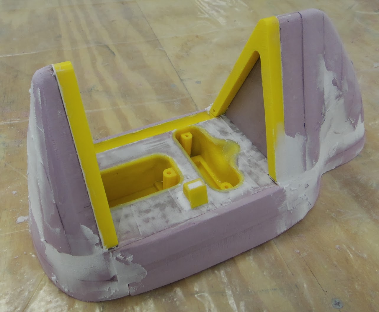
Today I also completed the installation of two small cargo pockets in the interior of the body.  These will come in hand for storing water bottles, keys, garage door openers, etc. when I am driving the velomobile.  It will also give me a place to mount the turn signal switches and hold the battery pack that will be needed when I wire those lights up. 


The work in putting the storage compartments together was not in the installation of them put just making the individual parts for each body  pocket.  I started with a piece of one inch styrofoam and then fiber glassed both side of a 5 1/2 inch by five foot piece.  Then I cut out the six pieces needed to match up to the inner ribs of the body.  These pieces then had inner foam removed so that the micro-balloon mixture could be inserted into them for the exterior white faces that you see in the photos.  It was simpler to do this step on the work bench then try and do it once the parts had been installed.  I hot glued the parts in place today and then puttied and glassed them to complete the job.  Looks pretty good and will come in handy in the velomobile. 
  So I've managed to get another couple of things crossed off of my to do list on the project.  Not big steps but good steps just the same. 

Monday, November 4, 2013

TerraTrike Velomobile Rear Housing Mounted

With all that has been happening here at the Tinker's Workshop over the past week or more I was happy today to get to mount the rear housing for the tail lights of the vehicle.  This went rather smoothly and with the work completed on the insulating of the garage it took little time to warm the new work space up to a comfortable level. So let me show you how it all came together.


Here once again is a computer image of the tail light assembly that needed to be built and then installed on the velomobile.  The upper and lower portions of the assembly needed additional Styrofoam to get the correct shape to match the body.


Here is what the body looks like without the tail light assembly in place.  Just was not correct as it looks like it has been chopped off.  So with this new assembly it will complete the entire look of the velomobile. 


I started with two pieces of one inch Styrofoam glued together and recessed the tail and brake light housings into them.  Along with these housings an additional recessed strip needed to be added so that the door for the light housing could be opened and not jam up on the inner face of the assembly.


The door and door frame for the light housing were then positioned and marked out on the foam surface. This made is simpler to keep things lined up when it came time for final assembly.


In this photo you can see the additional foam that was added to the assembly along with the shaping that was needed for the two inches of base foam that I started with.  I had to keep checking this assembly with the body of the velomobile so that I could get the proportions as close as possible for shaping. 


With the recess strip in the base portion of the assembly the access door is easily able to be opened to turn the lights on or off.  This will also come in handy when batteries need to be changed in the assembly.  The door is held closed with a magnetic latch.


Once the foam had been bonded into place I removed the door as it was no longer needed in this portion of the assembly and could be put aside for safe keeping.


Lines were then marked onto the foam to give me a guide where to cut away excess material to start shaping the assembly. 


I used a small Exacto saw to remove what foam was not needed in very short order. 


With the help of a sanding block and a small rotary sander I was able to get the foam smoothed out to a pleasing shape.  At this point I was not so concerned out getting the shape of the assembly exactly right as I only wanted to get a general shape.  Final shaping will come after the assembly is mounted on the vehicle. 


At this point I added a mixture of resin and micro-balloons to make a putty for filling voids and building up low areas on the assembly. 


Once the assembly had dried over night I was able to mount it to the body this morning.  This was a simple process of using a hot glue gun and sticking it on to the tail end of the vehicle.  This was only a temporary set up as I knew that more of the resin putty mixture would be needed to bond the assembly to the velomobile permanently and make it easier for final shaping. 


Without the clear door or the lights in the assembly the back end looks like a giant mouth that is wide open. 


Here the putty mixture has been applied to the light housing assembly and the body.  This will make a nice light weight strong joint especially after it has been fiber glassed.  At this point I need to let it dry for another day and then I will start sanding on it again to shaped it further to match the body.  


In this photo you can see the difference in the lines of the light housing compared to the body.  The top surface of the body swoops down more at the rear so the housing will need more sanding to match it's shape. This is not a difficult task as the foam and fiber glass resin putty mixture sand pretty easily.  Just will take a bit of time.  


The top view of the housing and the body line up very well.  Not a lot of work to do here to get it all in shape. 


Again another good view of the assembly on the body.  The upper portion of the housing foam will need to be tapered a bit more but with some sanding and a bit of time this will all come together. 


Once I get the top portion of the assembly sanded to my liking I will turn the entire body upside down once again to work on the bottom to match it up as well.  I am really glad at this point to be able to work in a garage now that is warm enough so the work can continue on.  Once I get all of the rear end shaped up properly I'll post more photos of the progress.  Hope you enjoy the photos and come back to see the next installment of the project.