Sunday, February 5, 2017

My Planet Express Project Is Completed!

I finally feel like I have caught up a bit in the shop today with the completion of my Planet Express project.  This as most of you may recall is a poster that I plotted out on Mylar film and then planned on enclosing it into a lighted frame to hang on the wall.  So with out to much more detail at this point here is how it all turned out.


Inside of my 18" x 24" lighted display is a string of controllable LED lights to give me whatever color strikes my fancy.  But I am jumping ahead here so let me show you the process it took to get to this end result.


 I started with a line drawing I had created from a poster that I had found online of the Planet Express ship from the TV show Futurama.  I liked the poster but I wanted to be able to light it from the back so I created a line drawing of it and printed it out on to Mylar film using my "Tooli" plotter shown above.


Next I gathered up the materials that I needed to make the wooden frame to make the "Light Box" so to speak.  This for the main part is 1 x 4's for the outer frame, two Plex-glass sheets and some 1/4" plywood. I cut the pieces to size to make a frame large enough to hold the 18" x 24" print and Plexi-glass.  I then clamped the first piece of 1 x 4 of the frame into my Kreg pocket hole jig that you can see above.


I've used this tool more times than I can count and it is as simple to use as putting your shoes on.  Clamp the wood into the jig after it is set up for the thickness you are using and then drill a couple of holes.


That's all there is to it.  Out come perfect pocket holes.  Nothing could be simpler.


Once I had the pocket holes in the upper and lower pieces of the light box I screwed the outer portion of the frame to them to make the frame you see here.


Next I glued in wooden plugs made specifically for pocket holes to fill them.


After the plugs had dried securely I took an orbital sander and smoothed everything out.  The bottom plug matched the color of the wooden frame so closely it's difficult to tell if it was ever put in.  The upper one still shows up but it did not matter as I had planned all along to paint the frame semi-gloss black anyway.


Here I started gluing and clamp the 1/4" round trim for the outer face of the display.


Again once the glue had dried all I needed to do was a little light sanding and the outer frame was complete.  I never needed to nail the 1/4 round in place as the glue worked out perfectly to hold all the pieces right where I wanted them.  Plus the fact that there is very little if any strain on the trim as it is only meant to hold the Plexi-glass display in place when it is used.


 I took blue painters tape next and covered all of the interior of the framework to keep paint off of it while I was spray painting the assembly black. 


 Once the painting on the outside of the light box was completely dry I could remove the painters tape.  It would have looked pretty messy on the back of the display had I not covered it up with the tape for sure.


At this point I was able to slide in the Planet Express print that was sandwiched between two pieces of thin Plex-glass. I had to make sure I didn't put this in backwards so it would be facing the right way when I completed the assembly.


Next I installed 1/2" thick  x 1 1/2" wide wooden strips to hold the Plex-glass/print assembly into place in the assembly.


The wooden strips were painted white before being installed into the assembly and were not glued in but rather simply screwed into place.  I thought it best to do it this was so that if heaven forbid that  I should ever needed to repair the display the print could be removed and remade or possibly a new design could be installed instead if I want to change it.   


The next step in the assembly involved putting in the LED light strip to make this display work the way I had planned.  The light strip has a sticky back to it but I found out earlier that this was not enough to hold the strip in place once the project was hanging on the wall.  Not a good thing to have fail once it is all buttoned up. So I had to work out another plan of action to hold this strip more securely.


I designed a simple clip that could be used to hold the LED strip in place and be simple enough to 3D print for the installation. Also be easy enough to install without having to make any modifications to the interior design of the display. 


I mounted the clips approximately three inches apart using #6 - 3/4" wood screws.  The clips for the LED strip only needed to be screwed in on one side as the back of the display boxed locked in the LED strip once it would be mounted into place. When I installed the screws I could feel the clear coating on the outside of the LED strip compress slightly. Then I knew I had it tight enough to hold the light strip in place. It took me longer to 3D print the 24 clips for this portion of the build than it did to install them.  No matter what, this was the perfect solution to secure the LED light strip and not have to worry about it moving out of position some time in the future.


The interior wooden strips gave me the mounting surface to install the back of the light box.  This was 1/4" thick plywood with the inner surface also painted white to reflect as much light as possible when the display was on. 


I figured out where the light controller needed to be before I closed everything up and made a small opening in the back panel so the wiring for the lights could be plugged into the controller seen here. Also in the photo above you can see two more wires.  The one in the middle of the picture is the sensor for the light controller so that I can change the display to different colors and the one on the right is the power cord leading to the power block that you plug into the wall. To hold the controller to the back of the light box I simply hot glued it into place. 


Here are several of the many different colors that can be shown with my new display.  The last thing I need to do yet is just install the wire hanger on the back so that I can put it up on my wall. 

This turned out to be a far easier project to complete and  than I had hoped for.  Nice to have that happen once in awhile to make up for projects that can be a pain to finish when you thought it would take half the time to build in the first place.  We've all been there more times than any of us want to think about right?  So enjoy the images and I'll enjoy my new display hanging on the wall.   Have a good day in your shop as well.


Saturday, January 21, 2017

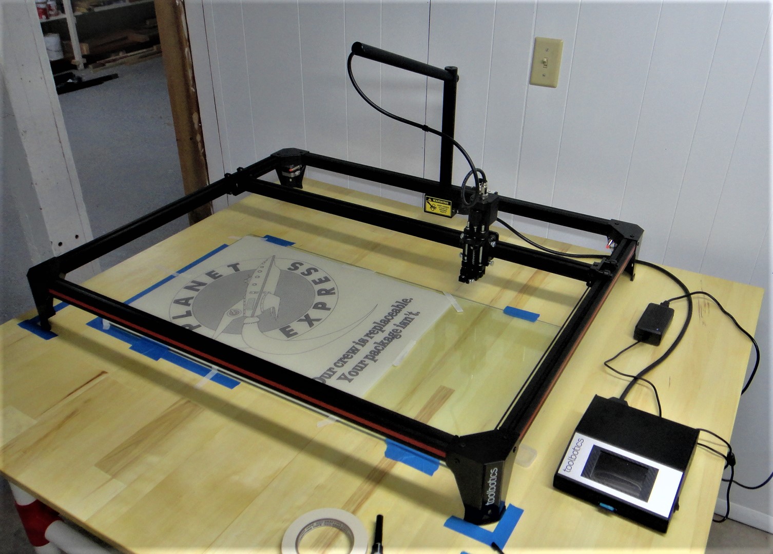
Toolbotics "Tooli" Making My Current Project Possible

Today while working on the Planet Express project I managed to complete the printing of the final Mylar inked print that I have planned for the project using my Toolbotics "Tooli" machine. 


I've always wanted a pen plotter that could create large prints and this machine is perfect for the job. Along with plotting it has quite a number of other capabilities that it can perform.  The machine that I own pictured above is the largest version which Toolbotics make that will handle a poster sized print. 


  The Toolbotics  company from Australia got it's business up and running through Kickstarter at least a year ago. That is where I first saw the machine and was immediately convinced that I wanted one for the projects that I create in the shop.   Along with plotting it has the capability to air brush images, laser engrave wood, laser cut paper, cloth and cardboard along with pick and place parts, and even extrude frosting to decorate a cake!
  I have just started working with the machine and have most if not all of the components to do all of these tasks and more so I have a lot to learn to get up to speed.  As for right now I am more than happy to be able to create the pen and ink line drawing on Mylar for my latest project.


The print you see here for the Planet Express project is 18 x 24 inches and it looks perfect.  I just have to set it aside for now so that I can keep it safe until I do the final assembly to display it. 
  The Tooli is a great machine and very well designed and built.  It will be fun figuring how to work with all of the different features that the machine has and will open up new capabilities for future projects.  For more information about the Toolbotics "Tooli" you can check out the link I've provided below.


Thursday, January 19, 2017

Planet Express Lighted Display Project

I wanted to get this post out before another day goes by so that I can keep you up to date as to what I have been working on in the shop lately.  First off the Goldwing cooler project is still progressing nicely as the painting of the cooler is coming along slowly.  I will post the final build on that project just as soon as I am happy with the end result.  But for today I want to share with you another new project that I have been thinking about for some time and have managed to put some hours into this past week.


  I call this the Planet Express lighted display project. I am a big fan of the show Futurama and of course the spaceship from the show.  I came across this picture online of a poster that has been around for some time of that spaceship.  I like the poster but I wanted to make something similar but also a bit different.  So I thought why not do a line drawing of the poster and then backlight it using LED strips in a frame.
Here is what the line drawing looks like after I reworked the design using my computer and a lot of effort to get the cross hatching the way I wanted it.  I printed off a 18 x 24 inch copy of the drawing on my plotter several times to get all the detail that I wanted in the drawing correctly done.  This was quite a task in itself as it took a little over an hour just to print one copy of the drawing and I went through four prints before I finally got it all worked out.  This does not even include the hours that I spent just creating the line drawing itself.


I plan on reprinting the drawing hopefully for the last time on to Mylar film using my plotter once again and a drafting ink pen. Once this is complete I will taking the print and sandwiching it between two pieces of Plexiglass and mount it into a framework that will also hold a LED light strip.  This light strip which will wrap around the inner perimeter of the light frame. It also will be behind the plexi/print sandwich assembly and the light frame that will have a backing board at the rear of the frame.  The Mylar is just translucent enough to allow light to pass through the material to give the display a nice even look.   I could have used a paper print but the paper itself when lit from the rear shows all the paper fiber.  Not the look I want in the project.  
  One of the pluses already with the print for the project being 18 x 24 inches was that the Plexi glass that I picked up today was exactly the same size so it simplified part of the construction.
  I have the led lights on order and I will have to pick up the wood for the light frame to get the construction started in the next couple of days.  I also will have to wait for the drafting pens to show up so I can make the final print of the drawing.


Here's a short little video that I put together of the line drawing on my plotter.  Kind of fun to watch if you've never seen a plotter running before.  I could not show all the detail as again it takes over an hour to do the entire drawing with all the cross hatching that is in it.


Here's a good computer image of what I have in mind for this project.  The green lighting or any other lighting for that matter would be generated by the mulit-colored LED lights within the display.  This will be controlled by a small remote so that I could pick and choose whatever color strikes my fancy for the day. 


So that's the latest update for this week.  I'll post more once I get this project started in earnest in the shop.  Have a good one.

Friday, January 13, 2017

The Blender 3D "Holli Project"

I've been wanting to get this post out for the last couple of weeks to kick off the new year with another video tutorial and this one is a good one.  I call it the "Holli Project" which is my idea of a holographic device that I created an image of using Blender 3D software.


I liked what I managed to create here in Blender so I thought I would pass along my learning experience to all you Blender users to show you how I put it together. 


Here is part one of the video tutorial for the "Holli Project".  I had to split it into two videos as it got to be to large to set up as just one. 


Here is part two of the "Holli Project".  Both videos will walk through the process of creating the holographic lady that is shown in the first picture in this post.  The first video is around 20 minutes long and the second is 16 minutes in length. 

 Click on the images for a larger view

Here I've included images of the node setups that are used in the video tutorials.  The image above is the nodes that are used in the compositor to combine two scenes into one image. Once scene for "Holli" to make here glow and another for everything else.  Just follow along in the video and it will make more sense.  It took me awhile to figure all of this out but after you get into it the fog begins to clear and starts to make sense.  Again watching the videos help a lot.


The image above is the node setup to make "Holli" glow.  A simple node setup compared to the compositing node setup.


Lastly here is the note setup to get "Holli" to be seen only by herself without any border or background around here.  Without this it would not look correct in the Blender render when it was completed.


In the first video I talk about taking a photo of a lady (seen above) and converting it to a black background for the project.  I was fortunate enough to find this image with a white background and then do the conversion.  But after doing this I realized that a lot of people would not have this image or may have an image that has a background that they want to remove.  So I tracked down the link below online to show you how to remove a background for this project or something similar using Gimp.  Gimp by the way is a free photo editing software that is similar to Photoshop.  Again being free works for me anytime and you can download it online.


Here is what you'll create in Blender from the video tutorials I put together.  The first image is like the original only with a black background and the second is what is called an "Alpha Mask".  Without this second image it would not be possible to create what the final Blender render looks like. So if you find some interest in this type of Blender project follow along using the video tutorials as I took it nice and slow so it's easy to make what I created.  Hope you enjoy using them for you next Blender 3D project. You'll learn some new things along the way that will be handy for many other Blender projects.  Enjoy! 

Tuesday, January 3, 2017

A Small Tripod For A Very Small Camera

A couple of days ago I was playing around with a small action camera called a Mokacam.  This I acquired through Kickstarter and am just now finding the time to figure it all out.  In the process of shooting some test video I realized that I needed a small tripod to get better camera angles. I have a small tripod that I've had for years but I wanted something even smaller and lighter. 


I started going through various drawers in my computer room and came across this little suction cup device. I had purchased this on eBay some time back for a couple of bucks but found it to be near worthless as a mount for any type of video camera.  The suction cup just was not strong enough to hold properly.  But the swivel mount was just what I wanted for this little tripod.


The swivel mount was the only good thing about this little gadget as it was made of solid steel construction and I could easily remove it from the suction cup part of the mount.  It was just a matter of unscrewing it from the base.


I went to work once again on my computer using Fusion 360 CAD software to create the new mount for the tripod as shown in the images above.  It took me several tries to get the threads for the swivel head on the tripod mount the right dimensions to match up correctly to the swivel mount but it was worth the effort.  The legs are held in place using small machine screws that get fed into three mounting locations around the tripod head.  The holes for the legs themselves are a little oversized so that they pivot smoothly and do not bind.  

Here you can see the new 3D printed tripod with the original swivel mount from the suction cup assembly.


With the swivel mount in place on the new tripod the total height only comes to 5.25 inches tall.  The Mokacam then easily gets screwed on to the top of the mount using a standard 1/4-20 type mount.


The plus side to the swivel mount is that now it can be position in various angles to get the photos or videos that I am looking for.  It will come in handy in the shop when I want to shoot video and get a good wide angle view of the shop to show what I am working on. 


I designed the legs of the tripod so that they easily could be folded up to make it a snap to store when it is not in use.  The cost to 3D print the tripod was only a couple of dollars and with the swivel head I now have something I can use while shooting video in the shop or on the go and is small and light weight in the process.

It pays to look through storage drawers to scrounge for bits and pieces for projects.  I had completely forgotten about the suction cup attachment and had written it off as a lost cause years ago.  Now I find that it was worth holding on to it for this little tripod. You just never know what can be made from scrap parts, a little design time on the computer, and a 3D printer.