Wednesday, March 30, 2016

Captain America Ball Chair Project Pt. 15..... New Chair Accessories!


It's been a stretch since I last posted so I thought I'd better get caught up while I'm making more 3D printed parts.  During the past week or so progress has still been steady with my Captain America ball chair project.  With this progress has come some new ideas that will be installed into the chair while the work is moving forward.  One big addition to the chair will be the inclusion of an air ventilation system. This will circulate the air in the chair to help supply fresh cool air to the user. 


The air ventilation system uses two small computer fans that will draw air in from the bottom of the chair and the blow it into the interior.  The computer images above show the ventilation setup for one of the fans.  The fan is located in the yellow and silver enclosure shown on the left in both images above.  The air is drawn in through the grate, then transferred through the white plastic tubing and then exits out the red adjustable nozzle shown on the right of the images.  The red nozzle will be able to be rotated to direct the air either directly on to the user of the chair or away from the person using it.  This is similar to the vent setup that is used in most automobiles.  Simple and effective.


In one of my last postings I talked about the amplifier sound system that will also be included in the ball chair.  The image above is a  simple change to this setup that I will be making.  The outer cover for the amplifier I originally was going to cover with the same material that I am looking at for the interior of the chair.  The only problem with trying to do this with the amplifier outer cover is the shape would be difficult at best to get it covered in material such as what is used in a headliner for a car.  So instead I plan on painting the enclosure as shown and then adding the Captain America shield emblem again shown in the image above.


After finding the correct image of the shield online I 3D printed the separate parts.  I was able to get them sanded to perfection again using 600 grit wet/dry sandpaper.  After a couple of coats of primer, more wet sanding and finally the correct paint colors applied I ended up with the three inch shield that you see in the photo above after the glue had dried.  I'm very happy how it turned out.  I couldn't do much better than the way it looks so it's another win for the project.


Here's what the back side of the Captain America shield looks like.  It is very obvious that the part is 3D printed by looking at this image.  The studs on the back of the badge will make it an easy process to mount the badge to the face of the amplifier outer housing. I thought it best to set it up this way should I ever need to repaint either the shield or the housing in the future.  Not that I ever want it to happen but you just never know.


Another small assembly that I will be putting together in the next week or so will be the control panel for the three LED lights and the air ventilation setup for the chair.  The computer image above gives you a good idea of how this panel will look once it has been assembled. The panel itself will again be 3D printed, sanded and painted to give it a nice smooth look similar to the Captain America badge. 


The switches for the control panel simply slide and lock into place and can easily be removed if for some reason down the line one should stop working.  The symbols for each switch are again 3D printed on an insert that will glued in place once it has also been sanded and painted white.  A simple task which will give the face of the panel a good look.  The symbols show one dot for one single light, two dots for two lights, and a wavy set of lines for the air flow switch. If I want all three lights on I simply have to turn on both light switches at the same time.  Nice, clean and simple. Works for me. I'll keep making parts and you keep checking in from time to time to see how it's all coming together.  Have a good day in your workshop!


Saturday, March 19, 2016

Captain America Ball Chair Pt. 14..... The Wedge Mold Making Parts!

I've been making great strides in this project this week with the first three wedge shaped parts for the ball chair coming out of the mold.  I wanted to get this post out so I do not have a huge posting with delaying any further. So let's get to it.

 
This is the finished mold for the inner wedge pieces that will make up the interior for the ball chair. At this point the mold has been sanded several times and then sprayed with primer and then wet sanded with 600 grit sand paper several more times so the surface is good and smooth.

 
Next I applied ten coats of mold release wax.  This stuff is very much like automotive paste wax as it is applied the same way.  Wax on.... wax off.  You know the drill.  Already you can see a much nicer finish to the mold.

 
Finally I put on two coats of PVA mold release.  Gives the mold a near perfect finish.  The photo above is what the mold looks like after the PVA has dried.  Nice and shiny.


Now this was the moment of truth as far as my fiberglassing skills were concerned.  I laid down the first layer of 3 ounce fiberglass cloth. Then two additional layers of 8 ounce fiberglass cloth were added.  Each layer of cloth was laid down in on single piece.  I wanted to do this so that the finished part would be seamless.  The trick in getting it all down correctly without a lot of hassle was to start in the middle and then work my way outward while applying the resin.  The corners had to me handled carefully so as to not get any wrinkles.  It took a bit of doing but I managed it.


Here is a good close look at the first part in the mold.  Looks almost like carbon fiber only because of the dark gray primer under the part.  I was very happy at this point to have it look this good.  It took right around an hour to get all the layers into the mold the way I wanted them to be so I could start breathing again.  I had to hold my breath while fitting the corners and getting a nice clean layup.
 
 
After letting the mold cure overnight I started to take the first part out and had to get these photos.  Here you can see where I have already loosened the part from the mold as the color change shows in the photo above.

 
Here the part is nearly released from the mold.  The dark spot under the part is the only section that is still not released from the mold.  I only had to give the part one more little tug and it popped right out of the mold.  Total time to get the part out of the mold was only a minute or two.  I was thrilled it worked so well and was so easy to remove from the mold.
 
 
Here is how the part looked straight out of the mold.  The part has a very smooth finish and could be painted just as it sits but that is not my plan as all of the wedge shaped parts will be covered once the chair is assembled. Trimming came next.
 

I only had to take a sharp scissors to the edge of the part to trim off what was not needed on  the finished part.  Very light weight but still not completely trimmed to the size I want for the ball chair. The lip on the part in the photo above is three inches and I wanted to get that down to around two inches so more trimming was in order.

 
This photo shows the progression that I need to take to finish three of the six wedge pieces.  From left to right you have the mold,  then the part just out of the mold, the wedge shaped piece completely trimmed to size using a Sonicrafter tool and finally the underside showing the reinforcements that I will ad to stiffen and strengthen the part.
 
 
Here's a good shot of the underside of one of the wedges with the reinforcement foam already added to the part.  Once the foam has been added it will have a couple layers of 3 ounce fiberglass laid over the foam to give it the rigidity that I am looking for in the chair.  Only the bottom three sections of the wedge shaped inner pieces will get this treatment.  The upper three sections will not have any weight on them so the parts right out of the mold will do nicely for holding the speakers and LED lights that I have planned for the assembly. Also in all of the corners of all of the wedge pieces I have added four more layers of 8 ounce fiberglass.  This make the corners very sturdy and should do well when the parts are mounted to the interior of the chair.

 
Here are two of the three wedge pieces set up with the foam reinforcements ready to be fiberglassed.  The foam strip that I put in are only 1/2 inch thick and an inch wide.  I laid down 1/4 inch by 1 inch strips and then doubled them up to get the correct thickness that I wanted for this portion of the project.
  Once I have the fiberglass over these parts it should do nicely to get the strength that I want in each section.  Total hours on the project has risen to 250.5 hours now.  Even with that I still will have a lot to do before this project is complete.  But with the success of the  wedge mold cranking out perfectly uniform parts it will make the final assembly fall in to place when I get to that point.  Enjoy the update and have a good day in your workshop.  I know I have had another good one for sure.


Monday, March 14, 2016

Captain America Ball Chair Pt. 13.... Amplifier Enclosure

Todays post for the Captain America ball chair project covers the design and construction of the enclosure that I will need to mount the amplifier for the speaker system that I have planned.  This part of the project took me some time to figure out as well as construct and it still has some work to be done before I can call it completed.  Even with saying that I wanted to show you what I did manage to get put together yesterday on this portion of the project.

Pictured above are some good images of the little amplifier that will power my speakers for the ball chair.  The amplifier is around 5" x 5.5" x 1.5" in size so it is very compact and will fit nicely into the confined space that I have planned for it in the chair.   The enclosure that the amplifier shows in these photos looks good and is useful in mounting in a car or for home use on a shelf but caused me a lot of concern in figuring out how to mount it into this project.   So I decided to remove the black outer metal case and design my own setup.


In the inside of the ball chair will be six wedge shaped pieces one of which is as shown above.  I figured the easiest way to mount the amplifier was to add a small pod on the inside of one of these wedges so that I could have easy access to the controls of the amp.  In the lower image to the left side of the mounting pod face you will see a small port.  This port is the connection that I will plug into to be able to use my iPad so that I can listen to music or a movie while relaxing in the chair.  You could also plug in an iPod or something similar so that is the general idea. The enclosure for the amplifier needs to be able to be mounted inside of the outer pod and the metal case the amp came with just would not do.


This is the new enclosure that I finished 3D printing late last night.  The enclosure has a face plate that is bolted to the new housing with the amp mounted inside.  The face of the ball chair pod for the amp will be sandwiched in between the amp's face plate and it's housing to secure it into place. This was a much simpler setup than trying to use the metal case that the amp had come with.


    Just to get the amp enclosure 3D printed was a big enough job in itself as it took around six hours to print so I am happy that it turned out and the design looks like it will work. The image above give you a good idea of the space that is needed to have access to the housing once it is in place.  This will make it an easy task then to hook all the connections up and get it running without running into some kind of interference problems trying to route wiring where I want it to be.  
 
  Once I do get the pod and the wedge piece constructed and assembled with the new amplifier it is a simple matter of connecting the speakers and power to make it functional.  I've already set this up on my work bench at it is an easy task and works perfectly.  Now all I have to do is cross the "T"'s and dot the "I"s so to speak to make it all happen.  Another piece of the puzzle figured out and one step closer to finishing this project.


Sunday, March 13, 2016

Blender Triumph GT6 Model Progress

Today looked like a good day to buckle down and get back to work on my Blender Triumph GT6 modeling once again.  The weather here didn't convince me that I should be outside so it was a good plan from the start. 


Like the other Blender car models that I've worked on this one is not much different in it's construction.  The blueprint layout of the sides, front, back and top help a great deal to keep things moving along but like the other cars I've worked on the blueprints are far from perfect so I have to kind of read between the lines when it comes to putting a model like this together to make all the panel and parts look right in the model.  


The door panels went together very quick which is nice to see.  The parts of the car in red are what I have completed so far and are fitting together pretty well. The wheels are complete other than the brake drums.  One of which is in place on the front wheel in the image above. This makes it look a little more complete so it gives you a good idea of where I'm going with this model. Lot of little details make up a model like this and it's usually the little things that make the model more complete in the long run.


Here you can see how the model is laid out to match the side view of the car.  This side view I felt is the most accurate and so it is my main guide to model the GT6.  


This image gives you a much better idea of how the car will look once it is properly rendered with decent lighting.  The wheels here really look good with the lighting which is just a sample of what can be done with this Blender model. So at this point I am still playing around with the lighting and the floor and a million other things going on in my mind while it (the model) is coming together.  
Even though I am nowhere near completing this model I am encouraged that it is finally taking shape and starting to look like the car I once owned.  Hopefully in the coming weeks I'll have it mostly put together.  A labor or love to be sure as I owned this car for 18 years.  It was my baby and so I just had to take the time to put the model together in 3D.  Enjoy.  More  posts about this project as I get farther along with it. 

Tuesday, March 8, 2016

Captain America Ball Chair Pt. 12...... New Light Housings!

Today's post is the progress that I have been making with the Captain America ball chair project.  Specifically the housings for the LED lights that will be in the chair.  This addition to the project I had planned from the start of the project so that I will be able to read while relaxing in the chair.  The LED lights will be plenty bright with no heat to worry about and should last for a very long time.  There will be three individual LED puck lights that will be mounted in the chair.  With these lights will be two light switches to control them to get different light intensities.  Click on one switch and one light comes on.  Click off the first switch and click on the second switch and two lights come on. Then when you click on both switches all three lights will come on to give me three different light levels in the chair which should do nicely for this project.

 
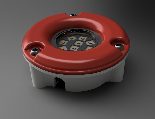
As usual I start out my work on any part for this or any other project that I work on in the computer.  This image of one of the LED lights for the ball chair I created using Fusion 360 design software. (Free from Autodesk by the way.)  Hopefully the real thing will look this good when I am finished with it. 

 
The parts for the LED lights are designed so that I will be able to mount them into the chair.  The white housing that you see above hold the LED light in place and the opening at the underside of this housing is for the wiring that will go from light to light when they are mounted.
 
 
Here is a top view of the same housing.  In order to print this I could have gone two ways with it on the 3D printer.  The upper flange on the image above mounts to the underside of the interior of the ball chair so in order to 3D print it I could either print it all in once piece as shown here or in two pieces and then bond them together.  I did the later as I thought it would be just as simple and cut down on the 3D print time which in itself was four hours for each of the three housings needed.

 
Here's another view of the same light.  The top red ring is also 3D printed and then sanded smooth and painted to give it a nice professional finished look.
 
 
Here's a shot of the real LED light that I am working with.  It is called a puck light and it is 2 3/4" in diameter and an inch thick.  I fired up the lights before I started the housing assembly and these little guys will put out more than enough light for the ball chair. Nicely made and easy to hook up.  I found them at my local Menards home and builder store.
 
 
Here the housing has been printed and one of the LED lights was inserted into it.  A very nice fit that is just what is needed for this part of the project. I inserted the mounting hardware (button head machine screw and threaded rod insert) at this point so that everything lined up properly when I want to bond the upper flange to the lower portion of the housing.
 
 
Here what the light looks like just after all the parts had been 3D printed and assembled.  Looks good at this point and everything fits up nicely. 
 
 
Another good shot show you all of the components to make up the light assembly all in one photo. In this shot you can see just how rough the red ring on the light assembly looks before it is sanded for painting.  Not that this is a bad part.  It is very smooth considering that it is 3D printed but with a little bit more work I know I can make it better.
 
 
Here is a good shot of two of the outer rings.  One without any sanding straight from the 3D printer.  The lighter colored ring is a ring that has been sanded first with 180 grit  sandpaper and then again with 600 grit wet/dry sandpaper.  Already it looks so much better.


Here the rings have been primed with thee coats of gray primer.  I do the final wet sanding on these part before I spray on the color coat of paint.

  
Now this is a great looking bunch of parts.  The work I did on the wet sanding really pays off now once you get to see the finished parts in living color.  These parts are totally dry and the finish is near perfection.  I will let these parts sit for about a week so that the paint will be at it's maximum hardness before I do the final assembly and put them back together with the LED light housings.  But it doesn't get any better than this when I can go from 3D printed parts and make them look like injection molded parts by just putting in a little time priming and wet sanding and painting.

 
This strange looking picture above is actually one of the housings for the LED light being bonded to the upper flange for the assembly.  The red rectangular part on top of the housing is a brick that I had laying in my garage.  It helped hold the parts firmly together until the epoxy/micro-balloon putty mixture cures and the part is ready to be used.
 
  So that's about it for today.  Another great step forward on the Captain America ball chair project.  One more quick note....  Progress is also being made on the mold for the six wedge pieces that I will need for the interior of the ball.  I have the mold built, sanded and three coats of primer done.  In the next couple of days I will be able to put the finishing touches to the mold and get it prepped to make parts hopefully by next week.  I'll post photos of that work when I get closer to laying fiber glass for the first wedge part.  Enjoy the photos and have a good day in your workshop!
 

Thursday, March 3, 2016

Captain America Ball Chair Project Part 11... It's Taking Shape!

After all this time working on this project today has been a very good day in the workshop.  The Captain America ball chair has been assembled for the first time! At least part way anyhow.
 
 
I was able to finally assemble all of the ring sections of the chair and start work on the mounting of the ball to the base today.  I am very pleased with how all the pieces are coming together at this point but as you can see I still have a long way to go before I can sign off on this project and sit down and relax in it. 
 
 
It's kind of a shame cover up all of the work that you see in the interior of the ball section.  There are only three joints in the ball but there are a total of 72 mounting plates that needed to be cut, drilled, aligned and bonded into the project so everything could be assembled easily. 
 
 
Shown here are the mountings for the dome section of the ball chair.  These have a threaded insert in a small wooded block and then the next ring has a mounting plate that the bolts go through and into the inserts of the dome sections.  This was the only way I could figure out how to mount these two sections.  Simple and it works.
 
 
  Here you can see a variety of mounts that I needed to set up for the project inside of the ball section of the chair.  The lower ring of mounts are for the dome section of the ball where the star will be painted on the center back of the chair.  The next two upper rings have mounts that are nothing more than 1/4 plywood bonded into the fiberglass sections.  The two larger mounts in the middle of the photo are the 1/2 bolt mounts that will hold the ball to the base swivel mount. These again were wooden blocks that were bonded into the fiberglass to keep them securely mounted in the assembly.
 
 
There are multicolored sections of the chair  at this point only because I have yet to do the finishing work on the pink and blue sections of the chair that you see in the photo above.  All of the parts have been fiberglassed and will need a finishing coat to fill the weave of the fiberglass cloth and then sanded smooth to prep it for painting.  The final prep work I will hold off on (wet sanding and painting) until I have some nice warm weather to take all of the sections outside.  It will be much simpler and a cleaner way to get the final work done before setting up the chair for the final assembly.
 
 
Even though the ball chair is nowhere near finished I just had to try it out.  I put a piece of Styrofoam in the base of the chair so I had at least something to sit on and took this shot.  It looks like the chair will be a good fit.  Just the right size and with the final inner sections mounted it will bring the seat height up to a good height.  Something I was concerned about when I started designing the chair.  That along with the opening diameter I think I hit the numbers right on the mark. 
   In this shot you can also see the outer blue lip of the chair opening.  I worked that out a couple of days ago and it has a good feel and look so more brownie points for me on that point.  I should be able to get the ball section mounted to the base in the next day or so to make sure that is all working properly along with the swivel mount.  I don't see any real problems with that portion of the build but you just never know.  I'll then pull the chair apart again and start on the finishing work and the prep work for the mold for the six inner wedge sections of the chair. 
   The light at the end of the tunnel is getting a little brighter every hour I put into this project.  Speaking of hours the number now stands at 176 hours for this project. Also I weighed all of the components  that I have on hand so far for the chair and it comes up to just short of 32 pounds.  This will increase though as the interior of the chair still needs to be installed so this will add to the final total there.  But I expect the chair to be under 50 pounds when it is completed and ready for use.  Not a bad weight to deal with if and when I ever need to move the chair.  Stay tuned for further installments on this project.  It'll only get more interesting from here on.