Thursday, May 23, 2013

CNC Machine Enclosure Project Video Part 7 Final Is Completed!

Today has been another great day here at the Tinker's workshop with the completion of another great project.  The CNC enclosure structure was finished late this afternoon after working on it pretty steady over the past couple of weeks.  The only things that need to be done to the enclosure is to either paint or varish?, install sound deadening foam, install plexi-glass upper window, and possibly install interior lights.  How can I say that this project is completed?  Easy as the list of things that need to be done are the simple things.  Just to get the structure designed, built, and assembled is the harder part of this project.  So the dust can settle once again in the shop while I put the finishing touches on the enclosure and get my CNC machine rebuilt and installed in this project. 

 Time to put my feet up and take it easy for a little while to catch my breath.  Check out the last video of the project and have a good holiday weekend!


For a larger view of the video go to the link at YouTube listed here.


Wednesday, May 22, 2013

CNC Enclosure Back Together Again....... With Doors!

A long day in the shop has been worth the effort with the CNC enclosure put back together again now with the new doors installed.  It took me some time to get the doors aligned properly on all the enclosure frames, windows in the front door installed and the entire enclosure put back together again. I was glad that I had laid out the framework before hand and had pre-installed it on the stand. This made the assembly with the doors simpler to do by myself. 


The CNC enclosure looks great with the doors all in place now.  The front windows worked out perfectly with no fuss to install them.


This is a good shot of the interior of the enclosure.  Lots of light coming from the ceiling light which  hopefully will be all that I will need to see what I am machining once I get my CNC machine up and running again. You can also see the triangular pieces of wood that hold the windows in place.  These are simply screwed into place without glue so that heaven forbid that I should ever have to replace a window all I need to is unscrew the mountings.


  Another good shot of the entire enclosure.  The platform below the enclosure will hold the electronics to run the CNC machine and also will be a nice place for other items to be stored in the shop.  I may enclose the lower platform as well just to keep things cleaner while working in the shop. Something to think about later on down the line.  In the mean time I will be working on part seven of the video sequence to complete the CNC enclosure and then on to updating my CNC machine so that it will work with the enclosure.  I'll post the new video once I get it shot and put together for viewing here.  Stay tuned and keep on tinkering!

Tuesday, May 21, 2013

Part 6 Video of the CNC Enclosure Build

 Not sure how many days I have spent on this project so far but I am still enjoying the journey so it really doesn't matter.  Just as long as I am having fun and able  to show you something interesting here its what it's all about.  That and the fact that I am getting closer to the completion of this project and giving my CNC machine a new home makes it even better.  Check out the progress today on the project by watching the video of part six at my YouTube link listed below.


http://www.youtube.com/watch?v=qnH_QAoSgQI&feature=youtu.be

Monday, May 20, 2013

The CNC Machine Enclosure Is Getting Bigger!

  I was doing some simple work on the Solsylva CNC machine enclosure build project this morning and just had to take a couple of photos of the progress that I made.  If you have been following the blog over the past week or more you will have seen the video segments of this build that I have been documenting.  I took this photo of myself with the enclosure to show you just how big it will be once it is completed.
  This enclosure is four feet square but from this photo it looks more like five feet square.    I stand 5' 8" tall and this is will be 6' 3" tall when completed.  Just barely enough ceiling height to do the job.  It will make a great addition to the shop and my CNC machine.  


The clamps on the enclosure in this photo were used to hold everything together until I got the internal metal brackets mounted in place.  So far it's looking great!
  The ceiling light you also see in the photo is in the perfect location for use with the enclosure once it is moved into it's final place in the shop. I will be able to put a window in the top of the machine and this light should illuminate the CNC machine in the enclosure when I am running it.  That is the plan anyway.  If the light is not sufficient I will just add additional lighting to take care of it.  More video will be coming shortly but until then I wanted to get this out to you.  Kind of a little preview of the completed project. 

Sunday, May 19, 2013

CNC Machine Enclosure Part 5..... Lots of New Assemblies!

Another good day at the Tinker's Workshop today with lots of progress being made on the CNC enclosure build project.  Check out the latest video of how the newest assemblies were made!


To see a larger video go to the YouTube link listed below.

http://www.youtube.com/watch?v=_QnTmQ1iS5E&feature=youtu.be

Thursday, May 16, 2013

Starting To Take Shape!............CNC Enclosure Build Part 4

Lots of progress with the CNC enclosure build has been happening here at the Tinker's workshop over the past couple of days.  Check out the latest video and you'll see how far I've gotten with the project!


See the video by clicking my YouTube link listed below.


http://www.youtube.com/watch?v=gOnu9Ecgw2c&feature=youtu.be

...

Monday, May 13, 2013

Parts, Parts, and More Parts.... The CNC Enclosure Build Video Part Three

Another big day here at the Tinker's Workshop as progress is still being made with the Solsylva CNC machine enclosure build.  In the video below you will see what I managed to get done on the build and I talk about more tools that I used for this project.  I have been showing part after part being made so bear with me as it will all make more sense in the coming days as the assembly starts  taking shape and all the parts that I have stacked up in the workshop will be put together.  Enjoy part three of the video build!


For a larger view of the video go to my YouTube link listed here.

http://www.youtube.com/watch?v=lhSeDqwetn0&feature=youtu.be

Saturday, May 11, 2013

Solsylva CNC Machine Enclosure Video Part Two


After a long day in the shop I managed to get all the 2 x 2 parts cut and trimmed for the Solsylva CNC machine enclosure build today.  The video says it all with every different kind of piece you can image that had to be cut.  Lots of saw dust..... five gallons worth to be exact so I got a real workout today with what all had to be done.  The next video will show all the pocket holes that need to be made for the build but this will be simple compared to what I went through today. Once all the pocket holes have been made then some plywood panels will need to be cut and assembly of the enclosure can start.  Keep checking in as I will do my best to continue putting video together for you.

To see a larger video of what I have posted here please go to my YouTube link listed here.


Friday, May 10, 2013

Solsylva CNC Machine Enclosure Video Part One


The Solsylva CNC machine enclosure project has gotten underway today!  This is a little video that I shot explaining the build and the first steps I had to take for the project.  This should be an interesting endeavour as this will be a fairly large build and I will do my best to document it in video.  So stay tuned for further video updates hopefully every few days. 

To see a larger video go to my YouTube link listed here.


http://www.youtube.com/watch?v=fv0b3EvST0I

Thursday, May 9, 2013

A New iPad Tripod Mount Accessory Is Created

A couple of months back I was experimenting with a new app for my iPad.  This app allowed me to create stop motion animation.  I have dabbled in this medium on and off over the years and so when I found this app and I knew that I wanted to work with it again.  The only problem I had with trying to use the app was holding the iPad still in one position to take the individual shots for the animation.  This turned out badly from the start as it was near impossible to do without moving the iPad and ruining the project from the start.  Inspiration struck at that point and another new project was born. 


This is the mount that I came up with for my Ipad.  It is adjustable so that you can use it either in portrait or landscape mode.  The mount is 10 3/4 inches long, 4 3/4 inches high, and 1 3/4 inches deep. It took around 12 hours to create using my Makerbot 3D printer and only weighs 8 ounces!  Best of all the total cost to make the mount came to just under $10.


The mount is made up of five printed pieces.  Two sliders (in white), two end caps (in blue at the top of the photo), and the mounting bar shown (in blue at the bottom of the photo).  The hardware that is needed for the project are two 1/4 inch x 2 inch machine screws, one 1/4 inch x 1 inch bolt, one small washer, two 1/4 nuts, and one 1/4 inch threaded rod connector.


 The sliders shown here in their correct orientation while using the Ipad mount turned out beautifully on the 3D printer.  Each of these pieces took three hours to print.  The wait was worth it I think. The parts were printed so that the square opening was pointed up while being made.  


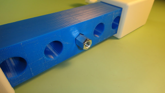
The mounting bar shown here is actually a pretty intricate part.  In the center there is a hole made for the threaded rod connector so that it slides in easily without binding.  Also on both ends of the bar are openings for the 1/4 inch nuts that need to be inserted from the two large outer holes that you see in the photo above.  The holes for these nuts are six sided so that the nut will not spin when the two end caps are mounted to the bar.


Here is a good shot of all the components for the mount.  The end caps have a extrusion that mates up to the recessions on the ends of the mounting bar.  This keeps the end cap from spinning once mounted to the bar.


After the nuts for the end caps have been inserted into the main bar the two sliders are mounted and positioned as shown above during the assembly the the Ipad mount.


One of the end caps is shown here ready to be mounted to the center bar.  With the 1/4 inch nut already inside the bar it is simple to slide the end cap into position and screw in the 2 inch x 1/4 inch machine screw to hold everything together. 


This is what the end cap looks like once it has been mounted and the slider moved to it's outer position.


Next the threaded rod connector is put into the center of the mounting bar.  This again is held into place with the 1/4 inch x 1 inch bolt.  This will keep the threaded rod connector from falling out.

Here the Ipad tripod mount is set up and ready to use as teleprompter in landscape mode. The threaded rod connector in the mount receives the standard threaded camera machine screw that is on the tripod.  It takes all of 30 seconds to put the Ipad mount onto the tripod or take it off.  


Here another shot of the mount in portrait mode.  The capability of the mount to change from one mode to the next is a simple matter of moving the sliders into position. 
  The mount will be useful as you see here but also for stop motion animation that I spoke of earlier.  I also have an app for my iPad that takes time lapse video.  Again this will be a great use of the iPad mount and should eliminate a lot of hassle in using the apps mentioned here.  Also this would work as a great video camera or photo mount using the iPad.  It will be a nice addition to my iPad and I'm sure I will find more uses for it as I go along.  Have a good day and keep tinkering!

Monday, May 6, 2013

Updated Fridge Calendar Project Completed

Another great project was completed this afternoon at the Tinker's Workshop.  If you have not been following along you can catch up now with this post of the Fridge Calendar project that I just put the finishing touches on.


The design looks great with the new look of the rectangular pieces shown here. 


Here is a good shot of the original design along with the new improved design.  The new version has almost the same number size, smaller over all size, and three times less weight. Plus the months can be displayed not too.


Here's a good shot of all the pieces that are needed for the perpetual fridge calendar. 100 pieces in all were needed to be printed and put together for the project. 


There are 162 total pieces to make the calendar which includes the printed parts and the magnets that are mounted on the back of each piece. These pieces were Super Glued on to the back of each piece from a magnetic roll after cutting them to size with a scissors.  There were 100 pieces to print on my 3D printer in the project which took 36.5 hours to do.  Then add at least another 25-30 hours design time and the project got to be a lot bigger than it looks.  I think the effort was worth it in the end.  Not that I would begin to duplicate this project to start selling them any time soon.  I would think a mold would be the order of the day as it would be a lot cheaper and faster to produce. No matter what this will make a nice addition to my kitchen that my visitors can enjoy as much as I do now. 

Thursday, May 2, 2013

The New Fridge Calendar Is Slowly Taking Shape

Today has been another long session of printing 3D parts for the Fridge Calendar project. Twelve hours to be exact.  A total of 100 parts will be needed to complete this project and at this point I am only up to part number forty-three.  This is what it looks like so far.


 It looks great already but printing the same parts over and over gets old very quickly.  Each of the smaller blue and red rectangular pieces  are the same and take 22 minutes each to print using my 3D printer.  The larger rectangular red pieces will display the months for the calender once I have the white inserts made.  These larger pieces take 34 minutes each to print so I am more than happy that I only have eight more to go.  Then on to the inserts for all the pieces.  Luckily each of these are different and will make this portion of the project a bit more interesting.  


The upper photo shows what the new calendar will look like once it is completed and the lower photo is what I have on my fridge right now. The new design looks a lot more up to date with the rectangular design and is a third of the weight of the original design.  Another thing that will be good with the new design is that the numbers and letters are all the same size as the original design but because of the new shape the amount of space that is need to display the calendar is reduced in size.  Hopefully I will complete this project by the weekend and I can get it put up on my fridge at that point.  I'll also keep a running tally of the hours I have on this project and be able to tell you the total cost to make this unusual calendar then too. Check back here to see the finished project.