Monday, April 23, 2018

Fusion Drive Spaceship Pt. 5..... A Redesign Is In Order!

I thought it best that I get this post out as soon as possible simply because it has been a bit longer than normal for my postings and the fact that I have run into a snag with my latest project.  The Fusion Drive Spaceship was completely assembled yesterday.  This was good and bad news all at the same time. The good news was that I was able to assemble it.  The bad news was that I needed to disassemble it and plan a new strategy to improve the model.  First some photos of the model itself.


After a lot of work I managed to get the paint for the front section of the model painted to my satisfaction.  I was most worried about getting the paint to lay correctly when it came to the area around the hatch.  As you can see from the photo above my efforts worked out very well.


The ring that runs around the mid-section of the model turned out very well too.  The paint that I used is called chrome aluminum.  Makes the part stand out very well and looks like metal.


The top photo is the rear section of the front  of the model and the bottom photo is of the exhaust cowling.  Both painted up nicely after sanding them smoothly with 600 and 800 grit sand paper, primer and several coats of gloss white paint.


This was also the case for one of the fins for the model.  I also figured out the name for the spaceship so progress was still being made at this point. 


Here are a couple of good photos of the engines for the spaceship. As you can see this is a large model to be sure. 


The cowling and the center exhaust were assembled using guide pins and glue.  The pins made this portion of the build a simple task as everything lined up as planned.  The engines for the model were assembled in the same manner.


 Here I started final or should I say my plans for final assembly of the model.  The base for the model is made up of three layers of .20 thick plastic spaced apart which was cut using a laser cutter.  This was assembled using standard 1/4-20 nuts and bolts.  The center post for the stand is a short length of PVC tubing that has a 3D printed mid-section that allows the tube to be mounted to the base using a three inch long 1/4-20 bolt.


Here the nose section is mounted to the assembly. Already the model was taking shape as planned with no issues. 


With the front section assembled I then installed the large fusion drive (light bulb).  All of my planning at this point went the way I had perfectly designed it. 


 Here the model assembly had been completed.  Looking at the photos anyone would say "Terrific! Good Job!"  I am sorry to say that the photos were better than the assembly at this point.  Trying to add the fins, motors, and center exhaust became difficult at this point.  I did not account for the additional weight of these parts.  Gluing them in place was not possible even using Super Glue.  This actually made things worse as the fumes from the glue fogged up the blue fuel cells.  The front section of the model was perfect but the rear section was only good enough to look at to take a couple of photos.  It was nowhere near strong enough to even think about leaving it as it was and expect it to last more than a couple of minutes. Way to fragile to say the least.  The model now had to be taken apart and rebuilt.

Along with this task the fins will have to be redesigned to be mounted using small bolts and nuts.  This I have already started work on.  I also have plans to modify the clearances that are needed for the light bulb to make the assembly stronger and easier to assemble. 

The center exhaust and cowl for the model will also need to be modified in the same fashion.  Once these have been redesigned I will set up assembly again before I paint the new parts and start again with new Fusion Drive Spaceship 2.0. So as they say.... "Back to the drawing board."


Thursday, April 12, 2018

Fusion Drive Spaceship Pt. 4....Even More Painted Parts!

Progress has been going very well these past couple of days on the painting of the parts for the Fusion Drive spaceship project. Lots of sanding and priming of parts have been the order of the day or should I say days this week but I am slowly seeing the end of this project nearing very quickly with my efforts.


Here once again is the front of the spaceship being sanded and primed for the second or third time. The top photo shows what the piece looks like after the primer has been sanded down.  The primer helps show the flaws in the parts or the sections that need to be sanded to get a nice uniform surface for paint like what you see in the bottom photo.


This nice shine black piece is the front windshield for the model.  I have already test fit this into the front section and it snaps right into place.  With it being already painted before I do the assembly it will be the exact look that I was hoping for when I designed the model. It would be near impossible to get this part painted to look like this once it had been installed into the model.


In the photo above is a number of parts for the fusion drive fuel cells (silver parts on the right) and fronts to the fusion drives on the left (silver) and their mounting rings (red).  


Here's a closer look at one of the fusion drive front sections.  These parts were completely  3D printed and required only a little effort to get them as smooth as what you see here. 


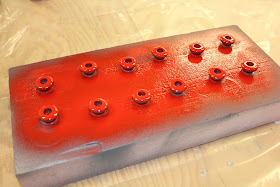
These twelve little button parts will be the end pieces for the fuel cells.  These parts actually were some of the simpler parts to prep for paint but needed to be painted upside down first and the right side up over a couple of days to get them to look the way they do here.  This took several days so that the paint would dry completely before turning them over but the wait was worth it in the end.


This rather handsome piece is the housing that mounts the fusion drive (large light bulb) along with the fuel cells for the spaceship. The entire assembly will really be impressive once all the components start coming together.


Here are the components that make up one of the fuel cells for the model.  The four white pieces are the end caps that were 3D printed the center rod with the red coil is a wooden dowel with a small plastic sleeve and the blue piece is the outer Plexi-glass tubing that holds everything in place. 


Here are the fuel cells completely painted and assembled ready for installation into the silver center housing I wrote about earlier.  These six assemblies have a total of 42 parts.  My planning paid off with these assemblies as very little gluing needed to be done to hold each assembly together.  All of them in place on the complete model will be quite impressive due to the detail that is in each assembly.


Here the fins for the model have been prepped for another coat of primer.  The orange blotches on the parts in the top photo are where I touched up the parts using glazing putty to fill any imperfections I found after the first round of sanding and primer.  In the bottom photo the fins are nearing perfection so I think they will be just about ready for paint very soon. 


This is the center ring that will be painted silver for the model and is very near ready for it's glossy coat of paint as well. This part has been sanded and primed a couple of times already and should be almost ready for paint as well.  I will have to inspect this part once again before I put my blessing on it but from what I see here it looks very good.

I'll keep plugging along with my painting but from what I have managed to get done already this week it should not be very long before I can do final assembly of the model.  Along with this in mind I am also working on a design of a carrying case for this rather large 26 inch +  long model.  I would hate like anything to drop this model as it would be destroyed in a heartbeat if that should ever happen.  All plastic and glass meeting a hardwood or concrete floor is not something I would ever want to have happen to my latest creation.  So a case will be in order.  Once I have the model completed I will immediately start work on the carrying case and let you know what I have planned when I am ready to start that project for this project.   For now enjoy the latest update.


Monday, April 9, 2018

Fusion Drive Spaceship Pt. 3..... Prepping For Paint

Work on the Fusion Drive Spaceship project has been moving along steadily this past week or so.  Lots of parts to sand and re-sand to get them ready for paint.  It's a long process but I know it will be all worth the effort once I can put the final assembly together and show it off at the next maker faire I attend.  But before I show you this progress I also have some new images of the completed spaceship that I put together a couple of days ago using Blender 3D.  So here you go.


I really like how Blender is able to get the finish and colors that are as accurate as what will be in the finished model.  Also with the lighting and sky background it shows off the model rather nicely too. I did try and put the spaceship in a space background but I was not happy with my results so this will have to do for now. 


 Here's a couple of good photos of the nose section of the spaceship.  The top photo is the part just after I 3D printed it.  This was one of the largest and longest parts that I had ever printed as it is 12 inches long and roughly 6 inches in diameter at the base of the part.  It also took 19 hours to 3D print. I am very happy with the finish of the part right off of the printer so there was not a terrible lot of sanding that needed to be done to get it ready for primer.


Here's what the nose section looks like sitting in my portable spray booth.  I primed it this morning and over the next couple of days it should be ready for a nice glossy coat of white paint. 


In this photo is the front windshield for the spaceship along with the windows, rear exhaust ports, and a small panel for the center exhaust port for the model.  The windows look good in this shot but I still need to do a little work on the windshield to get it just right.  Again just a little touch up will get that straightened out in short order. 


 These twelve red parts make up components that will be used in the six fusion canisters that are mounted on the mid section of the spaceship.  As the parts are rounded on the top the bottoms needed to be painted first and then let set to dry before the top of the parts could be painted to complete the process.  Time consuming but easy enough to accomplish in the long run.


Here the center mount for the fusion drive (large light bulb) has been painted and is ready to be installed into the model.  This was probably the easiest part on the model to prep for paint as there was very little sanding to get it ready to be painted and even then very little of the part will actually be seen once it is installed into the model. 


Here wing sections for the model have been primed for the second time and will still need some TLC to get them as smooth as I possibly can make them before I am happy with them.  Again a slow process as only one side of the wings can be painted at a time.  This actually makes it easy to paint them as runs would be a difficult thing to happen since they are laying flat to start with.  


Here are a variety of parts that will be used in the model that have been primed and re-sanded to get them ready either for paint or another coat of primer.  Starting in the upper left corner is the fusion canister mount, then the engine fronts and then the tail cowl that holds the ends of the wings along with the center exhaust for the model.  In the lower left is the fusion canister cylinder mounts and finally the rings that hold the engine fronts on to the body of the engines.  Again lots of sanding and prep work to get these parts ready for paint. 

Hopefully in the next installment of this build I will have all of the parts painted and be ready to assemble the completed model.  I am also planning on building a carrying case for this big project as I would shudder at the thought of having the model damaged in transport when I do take it somewhere to show it off.  That build will be another project in itself so that should be interesting and challenging as well.  So while I plug along on this build I hope your latest project is progressing nicely also. Have a good day in your shop!

Tuesday, April 3, 2018

Newly Designed Accessories Have Made Improvements To My Creality CR-10 S4 3D Printer


While getting to know my new Creality CR-10 S4 3D printer I have found it necessary to create some new accessories for it's use.  This mainly because from the very start I had installed a new Keenovo heater rather than use the stock heater that it came with.  This alone has been a wise choice to make simply because now I am more easily able to 3D print parts using ABS plastic instead of PLA.


With the addition of this new heating element I also removed the piece of glass that normally sits on top of the heated aluminum build platform.  I did not want to use masking tape to try and hold my parts down to the platform and hope that they would turn out ok.  Instead I chose to use a product from the Geckotek company that sticks to the build platform and eliminates the guess work out of trying to figure out what will or will not work to be able to make good parts.  So far I am very happy with this product.  With the glass being removed from the build plate the Geckotek build plate sticks right to it without fail.  But with the glass being removed now the adjustment knobs for the aluminum build plate did not seem to have enough tension on the spring that is mounted at each corner of the adjustment assemblies.  


To remedy this issue I added a #8 X 3/16" aluminum spacer underneath each spring at each corner of the build platform adjustment mount.  This put the tension back into the spring once all corners were adjusted for proper build height for printing.  These spacers I tracked down from another company named Widgetco Inc.  The item number for the parts was 10-8-187-AS.  These parts fit perfectly with the threaded bolt that is on the CR-10 S4.  Also pictured above I had modeled and 3D printed new adapters for the original knobs for these adjusters.  The original knobs seemed to be to small and to put it bluntly were a pain to try and adjust. The new adapters for the knobs are larger and much easier to adjust while leveling the build platform. These adapters slid over top of the original knobs and only needed to be press fit into place to set them up for use. 


One thing about the CR-10 S4 printer that kind of annoyed me while printing was the filament feeder tube that loops around the back of the main horizontal aluminum bar from the stepper motor to the extruder. It was the fact that this tube would drag across the heated build platform and your part while printing that drove me crazy.  This tube also had the capability to be able to snag onto a part (depending on the part shape of course) in it's original setup. I simply did not think it was a good idea that this part of the machine should drag across the heated build platform and my parts that I was trying to create.  To eliminate this issue I designed and 3D printed a small arm that mounted to the horizontal beam and keep the feeder tube from touching the platform or part completely.  A nice addition to say the least. This part was held in place using 5mm bolts and roll-in spring mounts for the extruded t-slot aluminum bar. 


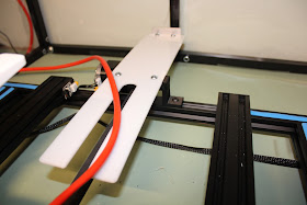
One last issue that I have corrected was the problem of the wiring for the Keenovo heater on the CR-10 S4.  Not that there is anything electrically wrong here it's just that the placement of the wiring on the heating element is at the center of the unit and extends toward the back of the machine once it has been mounted.  This causes and issue as to how to route the wiring to the outside of the heated enclosure. On the Creality CR-10 S4 all of the controls for the printer sit to the left of the machine.  There is enough orange cable (shown above) to do this but kind of gets jammed up either under the framework of the printer or around the stepper motor at the back of the machine when it is 3D printing. 

To eliminate this issue again I designed a guard that covers the stepper motor and lets the orange cable slide over the top while 3D printing.  This allows more than enough slack in the cable to move freely when the build platform is moving all the way forward or rearward as shown in the top two images.  The bottom image is the computer model of the new guard assembly.  The black 3D printed mount is attached to the bottom rear rail of the 3D printer again using roll-in spring mounts that easily connect to the extruded t-slot aluminum frame. 


I also added a small aluminum bumper on the to back of the cable platform so that the cable would not slide off of the end while printing.  This was created using a 2" long piece of 3/4" "L" shaped aluminum  to make the bumper. I bolted this to the 1/8" thick plastic using 10-24 1/2" bolts and nuts. This keeps the orange cable from sliding off the end of the guard when the build platform moves rearward while printing.   The two extrusions on the front of this plastic platform were required simply to allow clearance underneath the build platform for the mounting hardware that holds the drive belt for the stepper motor assembly.  Luckily the orange cable is very light in weight so there is really no issue with the plastic platform being overloaded which could damage it while being used. 

All of the additions I have mentioned here will go a long way toward an easier time 3D printing parts.  Less likely to have an issue in several areas now with the new parts for the printer.  Always a good thing to be sure.