Saturday, February 25, 2017

Blender 3D Helmet For Eye Glasses Concept Project

After having figured out how to put people into my Blender 3D projects I have already found a tangible use for this new skill set.  As a lot of you already know I am a motorcyclist and have been for many years.  Along with those years my eyes now are no longer as young as they used to be and so with my motorcycling I am forced to wear glasses.  Contacts are not an option for me so I have no choice and the prospect of Lasik eye surgery I am not fond of at all.  I have no problem with this other than the fact that putting my glasses on or taking them off after I have my helmet on is a pain.  With all of this in mind I thought that I would model a motorcycle helmet on one of my new Makehuman characters and see what I could come up with to make it easier to put my glasses on or take them off when I wanted to ride.


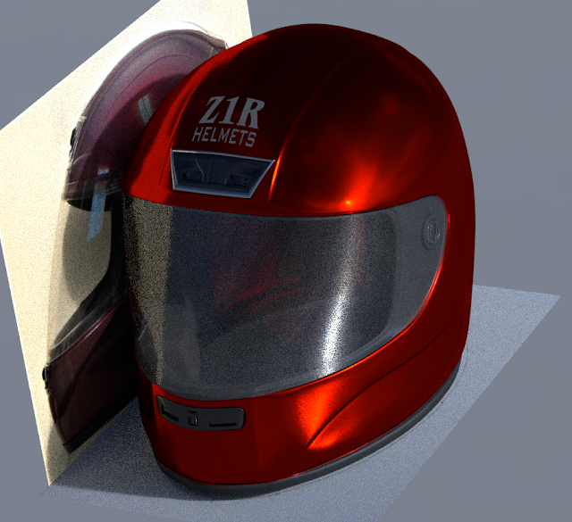
First thing was to get a good model made in Blender 3D to start with and then move on from there. This past week I managed to accomplish this portion of my idea to use in some concepting work that will follow. This is how my Blender model turned out.


It took me a few days to create what you see here.  Getting my motorcyclist modeled was the easiest part after having figured out how to get my character made in Makehuman and exported to Blender. The next step was figuring out how to model the helmet as close as possible to fit the character and resemble my own helmet in the process. 


I started by taking photos of my motorcycle helmet to get the views I needed for reference to get my Blender model scaled correctly.  I figured that with the helmet being symmetrical it would be easiest to model it the same way that I create a model car in Blender 3D.   I shot photos of the helmet so that I could get the top, side, and front views as straight on as I possible could.  That was the idea anyway.


I also took a photo of a tracing that I had made of the outer perimeter of the helmet's bottom edge as it set on a table. This helped out a great deal to get the model correct in all views. I then placed the views into Blender as shown to get the orientation and scale as correct as possible.


The only problem that I had to deal with in modeling the motorcycle helmet is that when a person wears a helmet it does not sit on the persons head the same way that it rest on a table.  The helmet is actually tipped downward at the front as shown above.


This made it a little more difficult to model but with a bit of finesse I was able to compensated for this issue by rotating the bottom and side view pictures and create the model as you see it here. The model of the helmet is very close to the actual helmet I wear with the exception of a couple of vents at the rear that I left out.  These were not necessary for the ideas I have to make a special mount inside the helmet for eye glasses.  That and the fact that these features are not seen in the front view anyway.


The added plus to making the model of the helmet in Blender is that I will be able to reuse the helmet in other Blender images or make a copy of it to create a new helmet all together for something like a space helmet for some futuristic space person.  So it will serve several functions with it's creation.


The modeling of the helmet once I got it set up with the reference images is very much like modeling a car.  The very same process is involved to get the features that I've managed to create.  It took me a couple of days but I am pleased with the end result.  One other thing that I wanted on the top of the helmet was the Z1R decal.  I knew that I could not get this on the model in my usual way so I tracked down a tutorial that I had saved for just such a purpose some time back.  Normally I would have UV unwrapped the helmet and then get the decal on that way.  But with the helmet being symmetrical and only modeled on one side this process would not work.  To see how I accomplished this I've included a link to the tutorial that I used to make it all work for those of you using Blender 3D. 


Not that I have the Blender model completed I can start playing around with ideas to make it easier for me to put my glasses on or take them off in the real world.  It's still just a spark of an idea at this point but at least I have something to work with in my computer to flesh out the project to see if it is even possible.  If I get something worked out I'll put out a posting on my progress.  In the meantime I also have another nice Blender model that I can use in other projects.   Have a good one!

Monday, February 20, 2017

Inexpensive 3D Printed Action Camera Hand Grip Project

Some time back I picked up a nice little action camera on Kickstarter similar to a GoPro but at a much lower price. The camera is called Mokacam and shoots in beautiful 4K video.  Impressive for such a small camera.  I have played around with the it a bit and plan on taking it with me this summer while I am traveling on my motorcycle.  I thought it would be interesting to use.  With this in mind I started looking at a hand grip for the little camera to help with this idea. Prices for a hand grip made specifically by and for a GoPro cost anywhere from around $25 - $30.  This would not do as the mount is all wrong for my little camera and the cost was also way out of line for what I had in mind. 
 
My computer design skills and 3D printer came to the rescue once again.  I worked out the design using Fusion 360 software and figured out what little hardware I needed to make my idea a tangible accessory for my little camera.


Pictured above is what the new grip looks like after some fancy design work in Fusion 360.  The hand grip for the camera is 1.25" in diameter and stands 4" tall.  This gives you a pretty good idea of how small the Mokacam is.  I really like using Fusion 360 as it is great software to design anything I can dream up and make a beautiful image of the project before it is even built so I can get my ideas out to all of you here on the blog before it is even built. Works for me.


I played around with different colors for the handle but in the end decided to make it entirely black.  But with the handle being designed into four separate pieces this made it simpler to actually print and make changes to individual parts as the project progressed. 


The hand grip is held together with a standard 1/4-20 bolt 4" long with a recessed nut in the upper section of the grip.  This was easily tightened down and held the assembly together securely. Also you will see in the images above that the inner red pieces of the grip have small  3D printed pins extruding out from them.  These pins eliminate the possibility that the sections will spin while assembled.  There are also two additional pins that are separate from the lower portion of the grip that needed to be made to serve the same purpose.  These pins could not be designed into the lower section of the grip as the 3D printing would not work correctly to recess the head of the 1/4-20 bolt in the assembly.


The Mokacam then was mounted to the protruding threads at the top of the grip by spinning it on to the camera mount that is in the bottom of the camera.  I had to adjust the amount of threads that needed to extend out of the top of the grip to get it just long enough to work but not to long so the camera could not fasten tightly to the top of the grip itself.


At the very bottom section of the hand grip shown above you can see the recessed area for the head of the 1/4-20 bolt along with two smaller openings.  The smaller opening have a hole between them so that the safety hand strap can be attached to the final assembly.  This will provide a bit of security to the should I ever loose hold of the hand grip.


Here's a photo of the finished grip along with a wrist strap that I had cannibalized from a dead point and shoot camera that I had in my work room.  I was very pleased with the 3D printing of the handle and the design itself.  I then calculated the total cost to make the handle.  The 4" bolt and nut was 44 cents and the ABS plastic to make the 3D printed parts for the grip came to only 66 cents. The wrist strap being free brings the grand total for this project to a spectacular $1.10.  This is a far cry from $25 - $30 for sure and I still ended up with something that I am happy with and will be even more happy to show off and use. Another great project and another good day at the Tinker's Workshop! 


Thursday, February 16, 2017

How To Put People In Your Blender 3D Models Video Tutorial

As a lot of you who have followed my blog over the years already know I am a big fan of Blender 3D software and what anyone can create with it.  The one thing that I have had trouble making in Blender for my creations has been people.  This I found to be a very difficult task and so I simply did not show people in my Blender 3D computer images that I created.  But as luck would have it I forced myself last week to slug my way through all the tutorials I could find on the subject online and after a couple of days things started to click into place. With that in mind I have put together what I have learned and made a video tutorial showing those of you who have had the same problem how to create people in Blender.
 
I had played round with another piece of software named "Makehuman" over the years and never could quite get it figured out.  It was easy enough to make a man, woman or child but I just could not get what I had created exported to Blender 3D easily.  Then if I did get something into Blender I could not change the scale of the person or pose them the way I wanted in the first place.  Again my research over this past week or so has paid off and I am able now to create any kind of person I can dream up and actually make clothes for them too.  Exciting to say the least for me anyway.


Here is one of the first characters that I created in Makehuman and exported into Blender 3D.  I thought this was terrific considering I had never gotten this far before and the results will fit my needs rather nicely when I want to model something where I want people in the images.


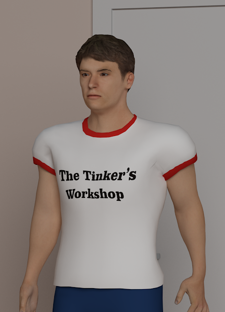
I then started playing around with the clothing on this first model and just had to put a Tinker's Workshop t-shirt on the guy you see here.  I still have a long way to go to work out new clothing but at least I feel this is a start.


I next went on to this young lady I call "Kathy".  No real reason for the name but at least I can call her something besides character # 2.   I brought Kathy in to Blender as I did with the first male figure and in the process streamlined the way I got everything to work in Blender to get the textures to come into Blender along with the Makehuman file at the same time.  Another big plus.  I cover this in the video tutorial that I've posted below.


When you run the video tutorial in YouTube be sure to click the 1080P button for a nice clear view of the video.

In the video I walk through the process that is needed to set up Blender 3D and Makehuman software so that the people you create in Makehuman can be exported to Blender 3D easily.  Also listed below are the links that you will need for the software and assorted files that are used to make everything work properly.


If you should have any questions about the process please contact me as I will be more than happy to help you along with making people for your Blender images.  Good luck and enjoy the tutorial.


Tuesday, February 14, 2017

Inexpensive Repairable Microphone Pop Filter Project

Yesterday I spent the entire day putting together my new Rode microphone arm assembly for the video tutorials that I do.  Not that it took me all day to assemble the arm. That was the easiest thing in the world to put together. Minutes at most.  What took me the rest of the day was designing, 3D printing, and assembling the microphone pop filter for my microphone that is mounted in the new arm.


For those of you who do not work with making recordings I will try to explain what a pop filter is and what it is good for.  A pop filter is a little mesh screen that is mounted between the person speaking into the mic and the mic itself.  This little filter reduces and or eliminates the popping sound that is heard on a recording when you say things like "Peter Piper picked a peck of pickled peppers".   These filters are not terribly expensive but if the filter gets damaged you cannot just replace the filter.  You have to replace the entire assembly that the filter is mounted in.  There goes x-amount of dollars down the drain.


So I decided to make or should I say remake a pop filter that I had constructed and used some time back. My pop filter set-up shown above is the finished project and I am pleased to say that it went together perfectly.  It will make things a lot easier for me when I continue making video tutorials or sound tracks for video that I have shot in the workshop. 


To get the project started I bought a simple 5 1/2" diameter plastic embroidery hoop.  This cost around $3.00 at a craft store. The mesh that is used in the hoop to make the pop filter is nothing more than black nylon stockings material.  Another couple of dollars.  I have used this set up as a pop filter on a previous project and it works perfectly. 

The isolation mount for my  microphone shown above has a steel ring that holds a collar that securely wraps around my microphone to hold it in place. This collar is held in place with elastic bands to isolate it from the outer ring and arm assembly to eliminate vibration that can also cause problems when making a recording.


This is a good shot of my complete microphone/pop filter/arm assembly.


As usual I worked out this project in my computer using Fusion 360 design software.  I modeled my microphone and only the ring of the isolation mount as I only needed this ring to figure out the rest of the assembly.  I did a little research and found out that a pop filter needs to be 2 - 3 inches from the microphone.  So  I came up with a simple upper and lower mount arrangement that would meet that requirement.  The two parts of the pop filter mount would clamp on to the isolation ring with a couple of 10-24 nuts and bolts.  Then the pop filter could be slid on to this mount and secured with the original thumb screw assembly as shown in the image above.


Here's a closer look at the pop filter mounting brackets for the assembly.  The upper and lower brackets have a recessed area on both parts that lock their arms around the microphone ring securely when the mounting bolts are installed and tightened.  On the end of the upper mount there are two indentations to accept the pop filter frame and a hole that is aligned with the thumb screw in the pop filter assembly.


Here's a good close-up view of the pop filter and mount with my microphone installed in it's isolation ring assembly. It's very solid and the fact that the pop filter is so light means there is no strain on the little mount to speak of if at all.  

The total expense to make the repairable pop filter and it's mount only cost a few dollars and works just as good as comparable filters.  The plus of course is the fact that it can easily be repaired if the need ever should arise.  With the 3D printed parts it is just a matter of reprinting them and the mesh can just as easily be replaced.  So it's a win-win kind of a deal for something that works great and is easy on the pocket book. Also the look of the assembly is pretty outstanding as well.

I thought it would have been nice to have the pop filter ring be black but I kind of like the orange ring too.  It gives the assembly a little color to brighten things up a bit.  I hope you've enjoyed this post and have a good day on your current project. 


Monday, February 6, 2017

Not Settling for "That's Good Enough"...The Micro-Cooler Project

In a lot of projects I build I am asked why it takes so long to complete whatever it is that I am working on. Sometimes it's because I am pulled away from a project because of some outside reason.  Such as my furnace or washing machine just died or I have to take an unexpected trip to resolve some other issue or I simply have other projects in the works at the same time that cause a delay and need to be completed first. 

But one of the main reasons some of my projects take as long as they do is because I've become somewhat of an perfectionist over the years in what I am working on.  Be it my latest artwork using Blender 3D or designing something on my computer to be built in the shop. This is the case with my motorcycle Micro-Cooler project that looks to be a simple thing to make but has been taking up a lot of time to get just right in my eyes. 


I do not consider myself to be an expert in what I do.  Not in everything I do anyway.  For design work I think I am darn close.  My Blender 3D artwork I consider myself to be an intermediate to advanced user.   For my work with carpentry, fiber glass composite work, and anything else I work on in the shop I think of myself as being again an intermediate to advanced maker.  It again depends on what I am working on at the time. I'm still learning and that is part of the fun of it all.


With the little Micro-Cooler you see here, I have been fussing with painting this project for far longer than most people would want to even think about. I'd wet sand, spray primer, wet sand again over and over until I am happy with what I see in the parts of the cooler.  Then finally shoot some paint and then find that I still have to do more wet sanding to correct either flaws I missed the first time around or that I just created because I laid down to much paint causing new problems.  So my work has continued with this somewhat simple project and in the process has taken more time to get just right.  I am sure that it is very obvious that I am not an expert when it comes to painting parts.  Not yet anyway.  I'm learning with each project that I work on in the shop and am getting better at each attempt. I keep trying and that is a good thing too.


With all of this in mind I am happy to show you the end result of my efforts at completing my  motorcycle Micro-Cooler project. This little cooler was designed and built to hold only a days worth of refreshment.  Small enough to fit into the trunk of my Goldwing motorcycle and still allow room for a full faced helmet too. 


I think the little Micro-cooler fits the bill rather nicely so the effort and time spent creating it matches up rather nicely. Enjoy the photos and like me you should never settle for "That's Good Enough".

Sunday, February 5, 2017

My Planet Express Project Is Completed!

I finally feel like I have caught up a bit in the shop today with the completion of my Planet Express project.  This as most of you may recall is a poster that I plotted out on Mylar film and then planned on enclosing it into a lighted frame to hang on the wall.  So with out to much more detail at this point here is how it all turned out.


Inside of my 18" x 24" lighted display is a string of controllable LED lights to give me whatever color strikes my fancy.  But I am jumping ahead here so let me show you the process it took to get to this end result.


 I started with a line drawing I had created from a poster that I had found online of the Planet Express ship from the TV show Futurama.  I liked the poster but I wanted to be able to light it from the back so I created a line drawing of it and printed it out on to Mylar film using my "Tooli" plotter shown above.


Next I gathered up the materials that I needed to make the wooden frame to make the "Light Box" so to speak.  This for the main part is 1 x 4's for the outer frame, two Plex-glass sheets and some 1/4" plywood. I cut the pieces to size to make a frame large enough to hold the 18" x 24" print and Plexi-glass.  I then clamped the first piece of 1 x 4 of the frame into my Kreg pocket hole jig that you can see above.


I've used this tool more times than I can count and it is as simple to use as putting your shoes on.  Clamp the wood into the jig after it is set up for the thickness you are using and then drill a couple of holes.


That's all there is to it.  Out come perfect pocket holes.  Nothing could be simpler.


Once I had the pocket holes in the upper and lower pieces of the light box I screwed the outer portion of the frame to them to make the frame you see here.


Next I glued in wooden plugs made specifically for pocket holes to fill them.


After the plugs had dried securely I took an orbital sander and smoothed everything out.  The bottom plug matched the color of the wooden frame so closely it's difficult to tell if it was ever put in.  The upper one still shows up but it did not matter as I had planned all along to paint the frame semi-gloss black anyway.


Here I started gluing and clamp the 1/4" round trim for the outer face of the display.


Again once the glue had dried all I needed to do was a little light sanding and the outer frame was complete.  I never needed to nail the 1/4 round in place as the glue worked out perfectly to hold all the pieces right where I wanted them.  Plus the fact that there is very little if any strain on the trim as it is only meant to hold the Plexi-glass display in place when it is used.


 I took blue painters tape next and covered all of the interior of the framework to keep paint off of it while I was spray painting the assembly black. 


 Once the painting on the outside of the light box was completely dry I could remove the painters tape.  It would have looked pretty messy on the back of the display had I not covered it up with the tape for sure.


At this point I was able to slide in the Planet Express print that was sandwiched between two pieces of thin Plex-glass. I had to make sure I didn't put this in backwards so it would be facing the right way when I completed the assembly.


Next I installed 1/2" thick  x 1 1/2" wide wooden strips to hold the Plex-glass/print assembly into place in the assembly.


The wooden strips were painted white before being installed into the assembly and were not glued in but rather simply screwed into place.  I thought it best to do it this was so that if heaven forbid that  I should ever needed to repair the display the print could be removed and remade or possibly a new design could be installed instead if I want to change it.   


The next step in the assembly involved putting in the LED light strip to make this display work the way I had planned.  The light strip has a sticky back to it but I found out earlier that this was not enough to hold the strip in place once the project was hanging on the wall.  Not a good thing to have fail once it is all buttoned up. So I had to work out another plan of action to hold this strip more securely.


I designed a simple clip that could be used to hold the LED strip in place and be simple enough to 3D print for the installation. Also be easy enough to install without having to make any modifications to the interior design of the display. 


I mounted the clips approximately three inches apart using #6 - 3/4" wood screws.  The clips for the LED strip only needed to be screwed in on one side as the back of the display boxed locked in the LED strip once it would be mounted into place. When I installed the screws I could feel the clear coating on the outside of the LED strip compress slightly. Then I knew I had it tight enough to hold the light strip in place. It took me longer to 3D print the 24 clips for this portion of the build than it did to install them.  No matter what, this was the perfect solution to secure the LED light strip and not have to worry about it moving out of position some time in the future.


The interior wooden strips gave me the mounting surface to install the back of the light box.  This was 1/4" thick plywood with the inner surface also painted white to reflect as much light as possible when the display was on. 


I figured out where the light controller needed to be before I closed everything up and made a small opening in the back panel so the wiring for the lights could be plugged into the controller seen here. Also in the photo above you can see two more wires.  The one in the middle of the picture is the sensor for the light controller so that I can change the display to different colors and the one on the right is the power cord leading to the power block that you plug into the wall. To hold the controller to the back of the light box I simply hot glued it into place. 


Here are several of the many different colors that can be shown with my new display.  The last thing I need to do yet is just install the wire hanger on the back so that I can put it up on my wall. 

This turned out to be a far easier project to complete and  than I had hoped for.  Nice to have that happen once in awhile to make up for projects that can be a pain to finish when you thought it would take half the time to build in the first place.  We've all been there more times than any of us want to think about right?  So enjoy the images and I'll enjoy my new display hanging on the wall.   Have a good day in your shop as well.