Saturday, December 31, 2016

Last Project Of The Year..... The Utility Cart Project

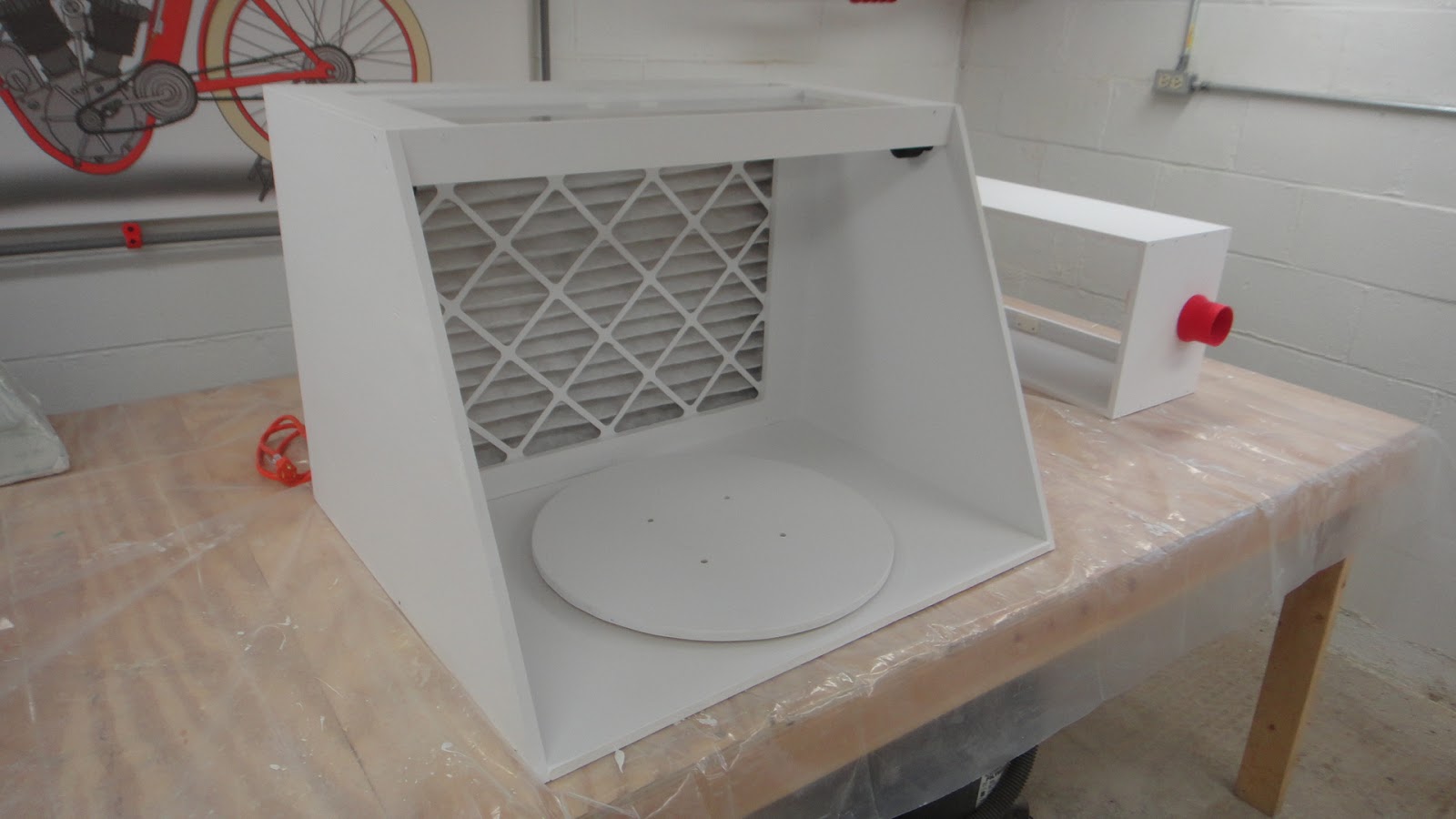
Being as this is the last day of 2016 it is fitting that I finish off the year with one last project.  If you have been following my blog over this past year or longer you will have seen one of my earlier projects which was a work table spray booth.  I have been using the spray booth now for a couple of weeks and I wish that I had built it years ago.  It's a great tool but with it comes a minus.  That being that the booth is awkward to move in or out of the workshop.  It's not terribly heavy just a big piece to move by myself.  With that in mind the utility cart project was started a couple of weeks ago and completed today.  So let's check it out.


As usual I start out my projects by designing them in my computer using CAD software.  In this case the project was designed using Fusion 360 software from Autodesk. (It's free by the way. Get a copy online for your next project.)  The cart had to be large enough for the spray booth and the window ventilation insert so I designed the cart with a flat top so the booth could of course sit on top.  I also made the second shelf lower so that I could put the window insert through the openings between the top of the cart and the second shelf.  I also wanted a nice handle to top everything off.

                                                                (Click on image for larger view)


Part#                Part Dimensions                  Number Needed

1.                     23" x 3.5"                                     (3)
2.                     2.5" x 31.5"                                  (4)
3.                     3" x 18"                                        (6)
4.                     3" x 31.5"                                     (2)
5.                     3" x 28.5"                                     (2)
6.                     3" x 30"                                        (4)
7.                     3" x 37"                                        (2)
8.                     4" x 5"                                          (4)


Here is an image of the cut layout for all of the pieces for the utility cart along with the dimensions and number of parts needed for each piece.  The entire cart can be built using only one 4' x 8' x 3/4" sheet of plywood.  From the cutting diagram above I was able to first cut all the parts out using my table saw.  This could also be done using a circular saw.  Once this was done I sanded all of the parts smooth using an orbital sander.  This took a little time but paid off big as it saved me the hassle of having to sand the cart once it was assembled which would have been much more difficult to do.


I started assembly with the front of  the cart.  This consisted of two #2 pieces (2.5" x 31.5") and three #3 pieces (3" x 18") laid out as you see above. 


Using a Kreg pocket hole jig I drilled all the holes that I needed for the first assembly.  The Kreg jig is as simple to use as a pencil sharpener and gives you perfect pocket holes every time.  Another tool that makes this project a simple one to complete.


I then glued, clamped and screwed the assembly together. Once the screws are in place the clamps can be removed and the assembly set aside.  This made putting the cart together a fast and simple process. I made two assemblies like this one and set them aside when completed and moved forward.


The next part of the assembly was to work on the sides of the cart.  This consisted of one #4 part (3" x 31.5"), one #5 part (3" x 28.5"), two #6 parts (3" x 30"), and one #7 part (3" x 37").  This last part I tapered on the end that sticks out in the photo above to make a nice transition for the handle that would be added later.  I measured the end length that was sticking out and tapered the ends inward by a half and inch.  (Check out the later photos of the completed cart to see how this ended up looking.)


Here are all of the sides that were needed for the utility cart.  The taper on the top side parts that I just spoke of you can see in the photo above.  This taper cut needs to be done before the side assemblies are put together.  Once this is done assembly is completed just like the front and back assemblies with pocket holes, glue and clamps.  Again these assemblies were set aside until final assembly of the cart started. 


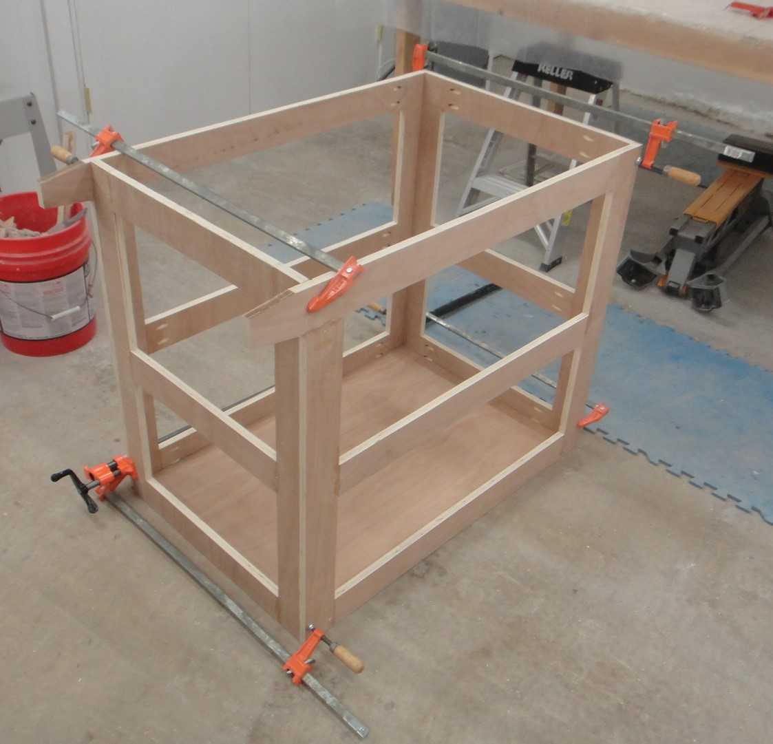
Here I started clamping the sides together along with the bottom panel in place.  The top of the cart as well as the shelves are all the same size.  This being the # 1 parts  (23" x 35").  I was happy at this point that all the care I had taken in cutting all the parts out was right on the money and the fit-up looked good.


I moved the first part of the final assembly up on my work table and started to glue, clamp, and screw the sides to the front assembly and the bottom shelf panel.  You can still see the clamp on the back of the assembly in the photo above.  The bottom panel was only put into position to keep the frame of the cart nice and square while the sides and front/back panels were assembled together.


Once I was happy with the framework of the cart I placed it back on the floor and clamped, glued and screwed the bottom shelf into place.  You can see all of the pocket holes that were need in this bottom panel in the photo above.  The pocket holes were place around four inches apart.  I took a while to put the holes in it but again was a simple process to complete.


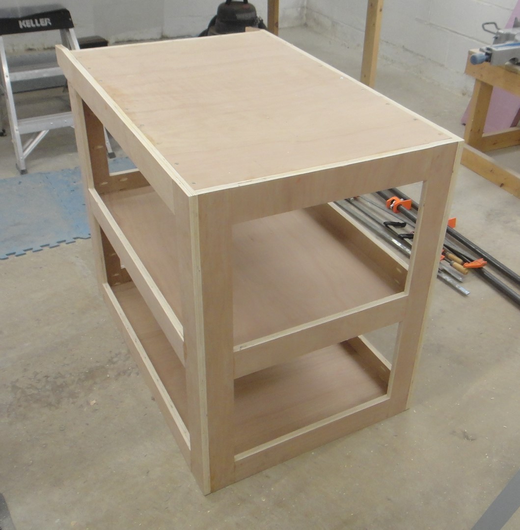
Here the cart assembly is nearly complete with the middle shelf and the top surfaces installed the same way the bottom shelf was.  I made sure all the pocket holes were on the bottom surfaces of the shelf panels so I could get a nice clean look when it was assembled.  The only other thing that I had installed in this assembly was two small strips of wood that ran the length of the cart from front to back underneath to top surface.  These I glued in and screwed in from the underside and the topside of the top surface using 1 1/4 wood screws.  Again I have a close up view of this in a later photo in this post. This was needed as the pocket screws caused problems with the top surface being flush with the sides of the cart frame.  Simply was not enough material to allow the screws to not poke out of the outer surface of the frame.  If the top surface of the cart was recessed like the shelves the pocket holes would have worked fine.  I just needed the cart to have a flat deck on the top so I had to have the extra bracing to get it to work the way I needed it.


With all of the major assemblies of the cart put together and assembled to each other I turned the cart upside down to mount the caster blocks as shown above.  I had some scrap 3/4" plywood that I had used but realized after I had mounted these that I could have cut them out of the original 4' x 8' panel in the first place.  But this worked just the same. 


I glued and screwed the mounting blocks onto the base and then screwed the casters on to the blocks.  Two caster for the front of the cart swivel and the two back ones remain stationary.  All of them using 3" wheels.


Next came the steps needed to install the handle for the cart.  I traced out the shape of the overhang on the upper rails of the top of the cart.  I cut these two pieces into shape with my bandsaw and then drilled a 1" diameter hole for the 21 5/8" x 1" long wooden dowel.  Along with this larger hole I need two more smaller holes that I counter sunk for the 1 1/4" wood screws to mount the blocks in place.


To install the handle all I needed to do was insert the dowel into the holes of the mounting blocks. I then applied glue to these block and moved the assembly between the overhanging parts of the top of the cart.  I slid the mounting block outward to mate up to the overhangs and then screwed them into place.  I clamped the ends of the blocks to get a nice tight fit.  After the glue had dried I used my orbital sander and evened everything out and rounded the outer corners off to get the shape that you see here.  Turned out better than I had hoped which is always a good thing in any project.


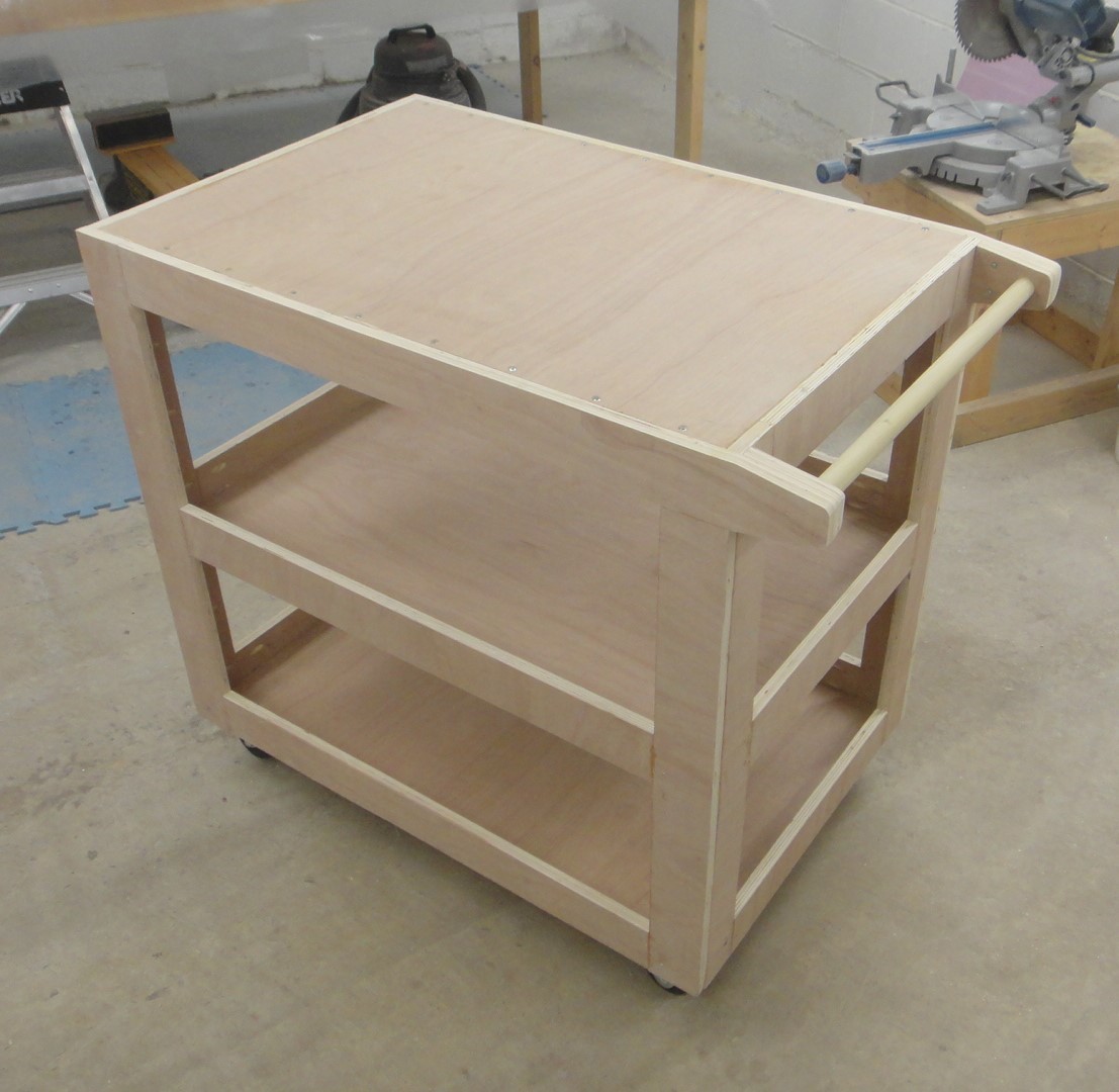
This is how the cart looked just before painting.  I was very pleased with my efforts at this point.  A nice new cart that should serve me well in the coming years in the shop.


After painting a couple nice coats of red paint this is how the cart really came to life.  I was fortunate enough to find a rubber mate that was exactly 2' x 3' in size for the top of the cart and had some left over vinyl wrap from a previous project to black out the handle as well.  Pretty spiffy don't you think?


The rubber mate is a good thickness and will protect the top surface of the cart when I haul stuff on it.  I have not found rubber mats for the inside of the cart but I am sure I can come up with something if I put my mind to it.  The top mat was only $7.00 so it was a good deal.


The casters for the cart work well and it's going to be perfect for the job I need it for.   The cart is 24" wide, 40" long with the handle and 36" tall.  A good sized cart to be sure.  These numbers could be reduced by adjusting the size of the parts that make up the cart if you wanted a smaller version.


This is a closer view of the top surface of the cart with the counter sunk holes for mounting the top surface.  I was just a bit happier with doing this mounting this way as it gave the top a nice look and worked well with the added bracing on the underside of the top.


Here's what the underside of the top looked like with the additional bracing strips that I had installed to the cart.  The pocket holes were there as well but realized as I said earlier that this would not work so the bracing strips were needed to get it all to work.

Well that's it for this year.  Another great project and a great year.  I'll be happy to bring in the new year and with it some more great new projects.  Have a happy New Year in your shop as well.

Wednesday, December 28, 2016

Something Fun From My 3D Printer

Now that the Christmas rush is over and the dust has settled a bit I thought it would be a good time to make something fun on my 3D printer.  With that thought in mind I starting thinking about a game I played with when I was in grade school a long time ago.  It was a simple game called "Instant Insanity".  It consisted of just four cubes with different colors on each side of each cube.  The goal of the puzzle was to align the four cubes and have four different colors on each side of the row of faces when you were done.  Not an easy task as I could recall so the puzzle gave me many hours of fun and frustration all at the same time. 
  I did a little research on this game and found out that it had been called by several other names over the years and had been produced much earlier than when I had first seen it.  So this was the project that I chose to make. 

Here is the layout for each of the four cubes to be used in the puzzle.  This layout I found online is a bit different than the original game that I first played with as the combinations of cubes also could be set up to have one color on each side of the cube when they are aligned as well as different colors on each cube as they are aligned.  So the puzzle could be played in two ways.


Each cube is made up of two halves.  The contacting faces on the inside of the cube have a 45 degree chamfer on their edges so the cubes will mate up nicely and be uniform on all side when glued together.  The circular indents on all six sides of each completed cube allowed for the placement of a colored disk for the game. In my version I also added four shapes to these disks as well.


Here is an image of the cubes with three already assembled in the background. Each cube is 1 3/4" square in size. They could be printed smaller but I thought this was a good size to work with as the inserts would have a bit more detail to them once they were installed into each cube.


Here are all of the inserts that I printed for the puzzle.  As you can see there are triangles, stars, hexagons, and squares all in different colors.  Twenty four pieces in all. Laying all of the parts out in the computer made the task of making this puzzle an easy problem to work on.  I used Fusion 360 software to get the job done.


To assemble the game I first glued all of the pieces for the black cubes together using plastic modeling glue.  After a few minutes the glue had did it's job and I could start gluing all of the colored disks into each cube per the diagram from the first photo in this post.  I did not have any green 3D printing filament so I substituted it for orange instead. 


The image above shows what the puzzle looks like as it is being played.  None of the sides that you see and even those that you don't see are correct...... and so the game begins.  The faces of the cubes that mate against on another do not matter when you play the game. So each cube needs to be twisted, turned, rotated, or position in a different location to complete the puzzle.  Hours of fun and an easy project to complete using my 3D printer. 

Now I just have to give it a new name as my puzzle is just a bit different than other ones that I have found online and played with in my younger days.  Maybe "Crazy Blocks" simply because it will drive you crazy once you start trying to complete the puzzle.  It's a thought.  Anyway enjoy the images and build one for yourself and see if you can complete this simple yet difficult puzzle.

Thursday, December 15, 2016

Merry Christmas And Happy New Year!


  2016 has been another tremendous year for my blog with all of you who have taken the time to read and see what I have been creating in the workshop.  The blog is now in its' sixth year and has received email and visitors from  over 95 countries from around the world.  As of this date there have been over  324,000 visitors to the blog directly and over 5.4 million visitors through Google+! 
  It is so nice to hear from so many of you who have written me and to each and everyone one of you who has visited my site I want to personally wish you a very Merry Christmas and a Happy New Year.  May all your ideas, dreams, plans, and projects turn out better than you ever expected.  I know my blog has exceeded my wildest expectations and I thank you all for its' continued success!  Have a great 2017 and I'll keep posting as long as I have people like you who want to know what I am dreaming of, designing and creating.

Sincerely,
Dave Langkamp

Monday, December 12, 2016

Model Car Headlights In 15 Minutes Using Blender 3D

The past couple of days I managed to solve a 3D car modeling problem I have been struggling with for a number of years using Blender 3D.  I always have had a problem with creating proper headlights for my car models.  What I did create was not bad but not great.  Great is what I was looking for and I found the last piece of the puzzle last night. 


Here's a headlight that I finally got my brain wrapped around using Blender.  The tough part about modeling a light like the one you see here is getting the lighting right and the prism effect on the headlight surface itself.  I did some investigating online yesterday and with a little bit of info that I did come across I started experimenting.  The end result is what you see here.


I was going to just create images of the workflow but instead I managed to put this video tutorial together to show you step by step how to create car headlights like the one above in under 15 minutes. When you run the video go to YouTube for a bigger view and also make sure you set the viewing to 1080P so the video is nice and sharp. 


For those interested here is the image that you will need to create the headlight that I made in the video.  Just do a right click on the image above and save it to your computer.  Also in the video I talk about a young gentleman named Andrew Price.   He is who I go to learn from and also who I got copies of the Blender Add-On's "Pro Lighting Skies" and "Pro Lighting Studio".  Great add-on for Blender which help turn out great Blender 3D images quickly and easily.  Here is the link to his site for more info.


Hope you enjoy the video tutorial!


Saturday, December 10, 2016

Back To Work On The Motorcycle Custom Cooler Project

Having just completed my work table spray booth project I'm now able to get back to work on my motorcycle custom cooler that I started back in October.  For those of you who have not been following the blog for very long, I started work on a custom cooler for my Honda Goldwing motorcycle.  The trunk of the bike is a good size but I could not fit a small cooler into the trunk along with a full coverage helmet.  So the project was born. I got to the point of the project where I knew that I would need to paint it and winter was already well on it's way so I set the project aside until the spray booth was completed.


Here's a couple computer images of the final design for what I've called the "Micro-Cooler".  The hinges that you see here are my own design that I printed using my 3D printer.  They are a bit of overkill but I think they look good just the same. The original hinges that I had purchased for this project just did not work as well as I hoped so I made these replacements and I'm happy I did.


I got the Styrofoam cooler parts cut and glued  together, then sanded all of the edges smooth to give it the shape to match what  I had designed in the first photos. 


The hinges turned out great and so no more work was needed on this portion of the project. Again the design is a bit more heavy duty than I need for this little cooler but I think the look is great  so I'll leave them the way they are.


In order to mount the hinges I first needed to make what I call "Hard Mounts" for the lid.  This is simply done by cutting out part of the foam on the lid and then mounting in wooden blocks and sanding them into shape to match the shape of the lid.


Then I mounted the hinges in place and marked out the hard mounts for the cooler box itself.  This way I would be sure that I had the lower hard mounts exactly where I needed them to secure the hinges properly.


I took my hot wire tool and bent the wire to remove the Styrofoam so I could install the lower hard mounts.  The fiber glass that I had laid up inside of the cooler could not be cut with the hot wire so it made this step in the project simply a matter of removing enough foam for the hard mounts.


Here in the photo I've attached the lower hard mounts to the hinges and puttied the mounts into the cavities that I had made to secure them.  I placed the cooler on it's front face to keep all the parts where I needed them while the epoxy resin cured. The photo above shows the cooler upside down so the lid is on the lower portion of the photo because of the coolers' position on the work table. 


After the hard mounts had cured enough I filled in any voids around the mounts with more resin putty mixture and let the mounts sit for another day. 


To get the name plate into the lid of the cooler again I designed it so it could be mounted into a cavity that I had made for the 3D printed name plate.  This will be bonded into the cooler lid once all of the fiber glassing , sanding and priming of the lid have been completed.  Then I will again lay in an epoxy resin putty mixture to fill any voids around the name plate.  Once I am happy with the installation of the name plate I will paint the entire lid white.  The final touch will be to paint the letters for the name plate in black.  A simple process with a small  paint brush should do the trick.


Lastly here is the cooler just starting to be painted in the new spray booth.  The cooler at this point had been completely fiber glassed inside and out and coated with the resin putty mixture to start the smoothing process before final paint.  I am happy at this point as this is the hardest part of the project. At least it seems like it to me anyway.  I will completely prime the cooler lid and all inside and out several coats at least.  Sanding and filling any imperfections that I find along the way.  By the end (I hope) it will turn out just like my computer image that you first saw in this post.  It will take a bit of doing but I know I will get it to my liking and will be more than happy when I do.   I'll post the final results of my efforts  to keep you up to date. 
  The spray booth by the way works perfectly and the addition of the turn table makes spraying parts a breeze. So that's about it for today.
  Have a good day in your workshop and good luck with your latest project as well.


Friday, December 2, 2016

The Work Table Spray Booth Is Completed!

I am happy to report that I completed work on the table spray booth project this afternoon.  The project went together without any major stumbling blocks along the way so that was a big plus as it always is on any project.  In my last post I had just completed construction of the spray booth itself. In this post we'll look at the assembly and painting of the window exhaust mount as well as the spray booth. 


This is the window exhaust mount that I needed to put together.  It is a simple box that I needed to build to have the exhaust hose from the spray booth connect to the workshop window.  I thought at first that all I would have to do is throw the hose out the window but as you will see in the next picture this simple would not work.


The window that you see in this photo is the closest window to my work table.  The window opens up from the top.  It unlocks and then tips inward at an angle from the top.  I thought the hose for the spray booth would fit between the top of the window and the window frame.  It was not even close so this box had to be constructed.


The 1/2" plywood box is 31" long, 12 1/2" high and 10 1/2" deep.  I still wanted daylight to come into the workshop so I cut an opening for a plexi-glass window.  On the end of the box I also cut a 3" diameter hole for the 3D printed hose mountings. The box was simple screwed together using  #6-1 1/4" deck screws. 


The hose fittings slid into the 3" diameter hole in the box with a nice snug fit and the red part and white elbow then connected to one another in the same manner.  It could not have worked out any better.


Once I was happy with the construction of the paint booth and the window exhaust assembly I primed and painted each with a couple coats of flat white paint.  I thought it best as the white will be nice and bright when I am spray painting to see easily what I am doing.   I can always repaint these assemblies some time down the road if I feel the need to spruce them up a bit.


Once the paint had dried I then started final assembly of the paint booth.  In the photo above you can see the lower exhaust fan and the mountings for the hose fittings.   These fittings were secured using zip ties that ran through the mounts and the back wall of the spray booth. 


Here the assembly is completed with the fans, connectors, hoses and electrical all in place. 


The electrical hookup for the two exhaust fans was pretty straight forward.  I wired the two fans together at the back using twist on wire nuts and then led all the wiring to the switch box.  From the switch box there is a power cord that is around four feet long  so it's easy to plug the unit in and turn it on or off. All the external wiring was then covered with protective split plastic tubing.  This cleaned up the look of the wiring and will give a little projection as well.


Here the spray booth is nearly complete.  All of the electrical is installed and the fans pump out a good amount of air.  In the photo above you can see light reflecting off of the Plexiglas window that I installed into the top of the spray booth to allow more light to come into the compartment. 


In this photo you can see the 18" diameter turntable that I mounted to the inside of the spray booth.  This was another simple task of just mount a bearing ring on to the wooden turn table and then mounting it to the inner base board of the spray booth using additional wood screws.  Should be a nice addition to the unit while I am spraying parts.


Here's an inside view of the window exhaust mount with the plexiglass installed in it now.   The plexiglass was just positioned over the hole and the brackets that I 3D printed hold it in securely with #6-1/2" wood screws.


In this shot of the paint booth interior you can see the mounts that I made for that assembly.  These mounts do not hold the window in but rather hold it up.  The window is dropped in from the top of the spray booth when it is sitting on the work table.  I could have mounted the plexiglass the same way I did the window exhaust mount but it would have been a smaller opening and I wanted to keep it as large as possible to allow more light to come into the spray booth while using it.  I also can cover up the plexiglass with clear plastic wrap to protect it from paint spray and then replace it as needed to keep things cleaner.


One last addition that I added to the spray booth was this hanger rod.   This is so I can hang small parts in the booth when I want to spray them. In the second photo you can also see the mounting tabs that I 3D printed to hold the plexiglass window in position.  I may put Velcro mounts on to these tabs and on to the underside of the window to keep it from falling out when I move the paint booth in or out of the workshop.  Not sure about that yet but it is possible to do.


Here finally is the end result of this project and another nice tool that will come in handy very quickly.  The window exhaust mount slid into the window frame perfectly.  This is actually a very quick process to install.  I simply have to remove the inner window which is about a 10 second operation and then slide the exhaust mount into the window frame.  It then is held in place using two small chains that are mounted to the window frame and the exhaust mount. 
  Again this part of the installation only takes another 10 seconds or so to do.  The nice thing about it is that the exhaust mount is fairly light weight and it rests securely in the window sill when I am using it.  Once I have finished painting whatever I am working on it can be removed from the window and put back to the way it was in short order.
  I really like the look of the spray booth and the exhaust mount. It looks good in the workshop photos above and still allows light to come in while using it. I'll put it to use very soon as I will need it to get back to working on the custom cooler for my motorcycle that I started before this project.  One thing leads to another but in this case it has led me to another nice tool that will come in handy when I want to spray paint parts any time the need arises.  Have a good day in your shop!