Tuesday, March 25, 2014

Velomobile Progress & Cradle Improvements


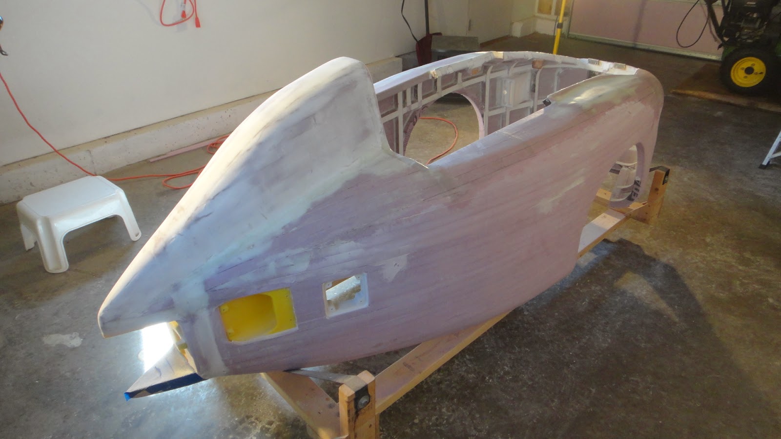
This week brings new progress to the velomobile project along with the  support cradle that I have for it.  With the build of the velomobile it was necessary to rest the body on to a special built cradle during it's assembly.  This cradle has made the build process much easier as I am able to move the body around in my garage very easily by having casters installed on the assembly. This cradle with it's nylon web straps hold the body securely without damaging it during the build.  But looking forward I find that the two inch casters will not do at all if I wish to work on the body outside of the garage and in my back yard.


To make it possible to roll the cradle out into my backyard when the warm weather finally shows up I decided to add a few more pieces to the cradle assembly.  I first removed the two inch casters and added axle assemblies made up of 2 x 4's and 1/2 inch plywood support plates. To these axles I then mounted seven inch wheels I found at my local Menards store. This makes up a rolling cart that also has the potential for some great coaster carts for kids.  I helped build a bunch of them when I was a kid so it was and easy thing to come up with for the velo build.


The front of the new cradle assembly is designed with a center pivot point that is steered using a simple rope mounted to the outer gusset plates. 


At the center of the front pivot point is 1/2 inch bolt that runs through the original framework of the velomobile cradle, several spacer blocks and into the lower front steering axle.  The spacer block was needed so that the front axle would swing freely when pulled from side to side using the attached steering/pull rope and not rub against the outer mounting bolts on the original cradle assembly.


The gusset plates for the front and rear axles were glued and screwed on to the axles and wheel mounting plates using deck screws.  A hole was drilled through the front axle gusset plate to mount the pull rope.


Here you can see how the axle for the seven inch wheels are mounted using 1/2 inch bolts through a small 2 x 4 block on each end of the axles.  These bolts are then held in place using lock nuts just tight enough to hold everything together but not so tight that the wheel does not spin.  The pull rope was fed through the front gusset plate on the front axle and then a knot was tied on the back side to hold it in place.


With this photo you can see how much more ground clearance that I have for the velomobile construction.  The seven inch wheels will roll nicely on my lawn now so I can keep the dust and out of my garage when the weather finally warms up and I want to do sanding or painting outside.  The new car only raised the body up six inches so it still is at a good working height.


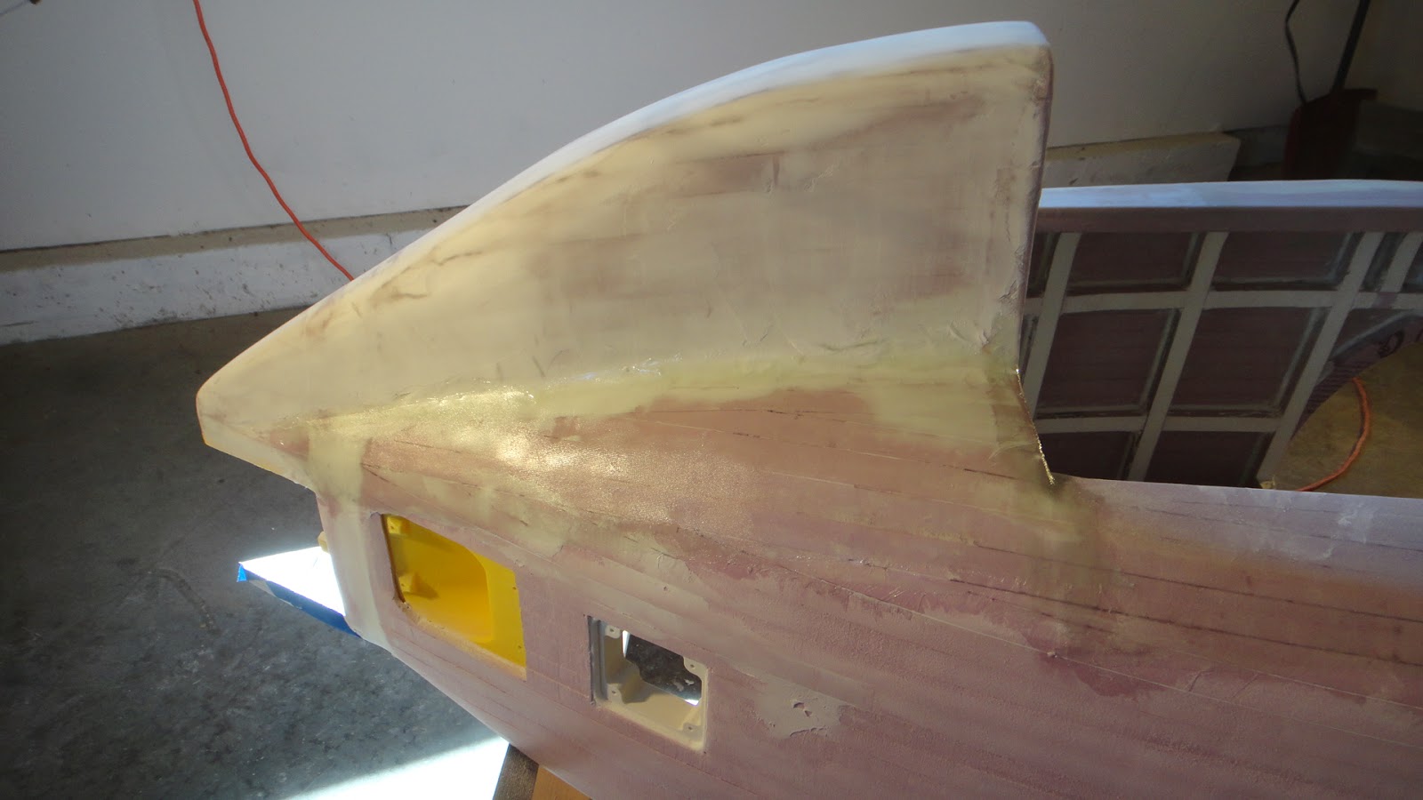
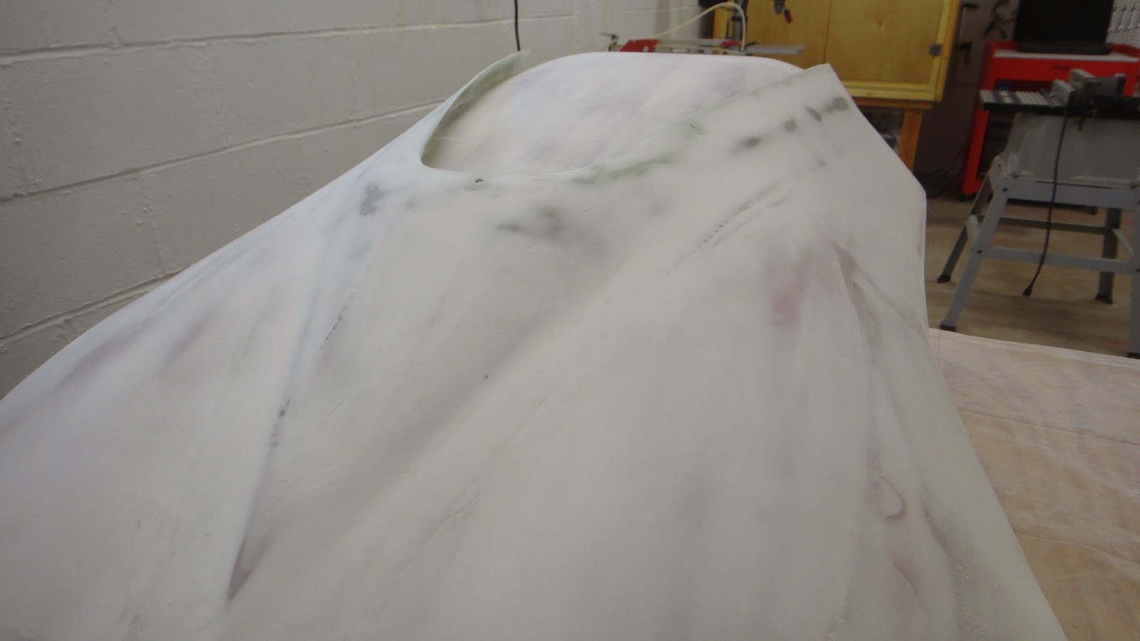
At this point with the build I have the velomobile completely fiber glassed inside and out. I will have to start the process of puttying the body to fill the weave using a mixture of micro-balloons and resin. and checking over any spots on the body to make sure I have not missed anything while I was glassing.  I also want to look for any imperfections that need to be smoothed out at this time too.  The rear blister behind the drivers compartment has already been done and has been sanded smooth.  This gives the body a nice white coating so I will be more than happy when the rest of the body is the same way.  Lots to do yet but with the new cradle improvements it will make it a lot easier and nicer to work outside under a shade tree in warm weather.  Until that time I'll keep plugging along in the garage to keep the project moving forward. 


Sunday, March 16, 2014

More Fiber Glassing Progress On The Velomobile

Yesterday was another big day of work on the velomobile project with a little over three hours of fiber glassing being completed.  As I have told many of you over the past couple of years since I've started my blog fiber glassing is not rocket science but it is very time consuming. I enjoy laying the fiber glass down and getting the foam in this portion of the project finally sealed up.  All of the final prep work to get the body of the velo ready for paint is where the real grunt work happens. 


Here's the body of the velo once again turtle side up.  The glassing of the underside went smoothly as there is very little fussing that needed to be done to lay the fiber glass down over the now upside down bottom edge of the body. Again you can see the difference in color of the glass on the foam from the top edge down to about six or seven inches below that edge.  I just took a look at how it turned out and it looks to be another good effort.


I was able to seal up the entire front end of the body with this go around of glassing.  All that needs to be done now are the sides.  I'll have to do some prep work around the housings for the lights and the access ports on both sides beforehand but this should not pose any real problems.  I'll also have to do some more smoothing of the foam strips to make sure the body is as even as I can get it at this point. The plus side to glassing the sides is that the areas will be laying flat when I lay the glass down.  Makes things a bit easier for this portion of the project. Again I will have to pick and choose my work days as today is to cold to even attempt glassing in the garage.  Hopefully some time this week I will get the body glassing completed. I'll let you know when this is done and how the next steps in the project progress. Have a good day in your workshop.

Thursday, March 13, 2014

Progress Once Again On The Velomobile

I had to do some back tracking on my blog to see when the last time I actually did some work on the body of the velomobile project.  It is hard for me to believe that it has been almost three months time.  Time sure flies when your trying to stay warm and not think about shoveling snow every other day.  So with a reprieve from this awful winter today I was finally able to get back to my garage and heat it up to a level that I did not have to wear a parka to stay warm.  Makes it a lot easier to lay down fiber glass if the brush does not freeze in my mixing cup. 


Here once again is my velo project in my garage as I worked on it today.  The progress again has to been done in steps but as you can see a lot of work has already been accomplished with this big project.  I have the entire interior of the body glassed now and all of the mountings for the lights and access ports for the the rear body mounts.  Along with this work I have completed the fiber glassing of the top surfaces of the body from nose to tail.  The tail section along both sides of the rear blister I completed today. 


You can see the difference in the color of the pink foam in this photo after it has been glassed.  It appears to be a bit darker when it is wet with resin.  I'm happy to get this last port of the upper body completed today after such a long absence of not working on this project.  Once this has cured for at least another day I'll turn the body upside down and glass the underside.  Then the sides can finally be glassed and the body will be much safer to handle.  With bare foam it can be damaged easily with just the slightest wrong touch. 


I thought while I was updating my progress on the velomobile I would also show you how the hood for the vehicle is coming along.  I have it all glassed now and most all of the resin filler applied to get a smooth surface for paint. 


This portion of the build is shaping up nicely and I am anxious to way down some primer to finish the prep work needed for paint.  The hood is very smooth at this point and the photos look like it's all ready to be painted.  In actuality it has a long way to go before I think it will be ready.  Lots of flaws will show up on the hood as well as the body once I start spraying primer on the parts.  This is good and I expect to have a lot a sanding to do yet to put my final blessing on the project and get ready to add color to velomobile.  Slow and steady progress will be worth it in the end.  
  I'm just happy enough to be able to fire up my heater in the garage once again after all of this time and finally be looking forward to spring, green grass, and warm weather.  Lots of things planned for the coming year so stay tuned for further updates as the weather allows. 

Friday, March 7, 2014

Testing, Testing, and More Testing

The winter continues to  drag on here at the Tinker's Workshop and so to work in the shop or my computer room on my latest project has been a far better thing to think about than shoveling snow or bracing for another round of sub-zero temperatures that everyone around the country has been putting up with.  


  My latest project that I have been designing and refining on my computer has been the reworking of an idea that I came across online some time back.  It is a working air powered motor similar to the one in the video shown above.    I like the design but want to rebuild it using parts made on my 3D printer.  I also want to scale the engine down to 1/4 or maybe 1/3 scale.  


My new engine design is much smaller in size than the one in the video.  The piston in the video is 5" square and in my version it is only 1.25" and is cylindrical as it should be.  I also believe that my design is much more air tight so it will be a bit more efficeint while it is running.  The flywheel in the wooden version is 15" in diameter as where mine is only 3.75".  A much smaller package all the way around.  Being also that almost all of the components of my version of this engine are plastic it will take much less air to make it move. But before I go into this further let's get to the testing part of this design and the reason for this post.


Here are all of the parts that I had to make just for testing out the fit and function of my planned 3D printed air engine.  There are test holes for the 6-32 machine screws that will hold all the parts together first. (Square part with three holes in it on the left hand side of the picture).  Next came a test part to make the capture cavity for the 6-32 nuts (next part right of the first part).  The little square part with an circular indent and the rectangular part with two holes in it are for the shafts for the piston, flywheel, crankshaft, valve slider parts in the assembly.  On the far right is a circular part and just below it is the actual piston for the assembly.  The circular part is a test part for the piston cylinder that needs to be made.  Lastly the six parts on the upper portion of the photo are test parts for the valve slider mechanism in the engine.  
  As you can see there is a lot of test parts here but in the long run it is much faster and cheaper to tweak these test parts than to make major parts for an assembly such as this only to find out it does not fit correctly.  A test part can take only a few minutes to make and save you hours of work by not having to reprint major parts that are bad from the start. 


This little engine when it is completed will only be 3.75" wide, 9.3" long by 4.125" tall.  A very compact engine compared to the wooden version.  Once I have the engine up and running only using air power (and very little air at that) I want to play around with using a compressed air bottle to make it run.  


In my Velomobile project I already have an air horn for the vehicle that uses a compressed air bottle that looks like a one liter pop bottle.  This little air horn comes from a company named Air Zound. I thought the same idea would work for this little engine to make it run.  But first things first I have to just get the little engine to run at all.  So it will be another interesting project to play around with until the weather warms up enough for me to actually get back to the garage to continue fiber glassing work on the velomobile project.  I'll keep you up to date as I get farther along with this project.  Stay warm and keep on tinkering.