Wednesday, October 30, 2013

TerraTrike Velomobile Speedometer Mount And More

With all the renovation that I have been working on in my garage to make it winter proof I have still been able to keep the progress moving along on the velomobile project.  One of the things that I  have had to figure out over the past months is where to mount the speedometer for the vehicle.  The original placement of the speedometer was near my ankles on the TerraTrike recumbent.  This worked out fine as long as I did not have to touch the speedometer for any reason.  With the body of the velomobile it would be near impossible to touch the speedometer much less read it in an enclosed body.  I found the solution to all of this and that is what I am going to show you here.


The speedometer mount is made up of seven different pieces as you see there.  The large blue piece is the main frame of the mount. The two top pieces in red are the mating mounts for the main frame.  The two yellow pieces are also mounted to the frame to hold the cylindrical spool (also in red) with an orange disk that will hold this spool in position.  The speedometer has a rubber strap that wraps around this spool and is locked in place.  


Here is the newly 3D printed mount assembled using standard 10-24 hardware.  I have also mounted the speedometer in it's correct location.  I like the look of the mount as the speedometer being all black the mount needed to be the same to make it all match perfectly.


The wire coming from the speedometer is the lead to the sensor that is mounted near the front wheel.  A magnet is attached to one of the spokes and as  the wheel spins the sensor picks up the magnetic field of the magnet and counts off the revolution per second and then displays the speed of the velomobile. 


Here you can see how the speedometer and mount are attached to the vertical body mount on the TerraTrike for the velomobile body.  The sensor wire is sent down this shaft and attached to a small mount near the spokes of the wheel.  This will make reading the speedometer much easier.  The mount allows for the speedometer to be position vertically, and can be rotated horizontally and vertically.  


This shot gives you a much better idea of where the speedometer is located when you are sitting in the velomobile.  I don't even have to remove the speedometer in order to remove or install the body from the frame of the TerraTrike.  A nice thing to know when I am getting it ready for the road. 


Another small assembly that I needed to get straightened out this week was the access doors that will cover the openings on the rear sides of the velomobile. (the square white openings). These access ports are needed so that it will be easier to mount or dismount the body from the TerraTrike frame.  


The original doors I was thinking about were to be a plain simple door and then fiber glassed.  The problem with this was the indentations on the doors for the mounting hardware to hold the door on the velomobile.  Fiber glassing these little indentations would have been a pain so I went with a totally 3d printed door and added some design features to it.  The mounting hardware then would be capped off with a cover to finish off the design.  A good look I think.


Here you can see all of the part plus one of the 4mm machine screws for the assemblies.  The eight pieces on the lower left are the finishing caps for the hardware.  The other eight pieces on the lower right are the inserts for the finishing caps. 


 Here you can see one of the machine screws inserted into the plastic mount for one of the finishing caps. These caps snap onto place and can be removed by prying them up with a small screw driver.


Here's how the access port doors will look like once they are assembled and mounted on the velomobile.  A nice clean look with just a bit of design to make it look more interesting. I will sand all of these parts smooth and then paint them to match the body. 
  Just a couple more things that I can cross off of my long to do list for the velomobile project.  Another good week here at the Tinker's Workshop.

Warmer Garage Work Space At The Tinker's Workshop

  It has been a busy week or more here at the Tinker's Workshop with more parts being made for the velomobile project, fiber glassing, sanding and fitting parts on the body and the list keeps growing. 
   With winter just around the corner I have also been working on prepping my garage so that I can continue work in the space without freezing in the process. I have the garage completely insulated now including the garage doors.  Not a fun task but one that will pay off with a much warmer space to work in when the snow is flying outside.
I finished installing another nice feature in my 24 X 24 foot garage this morning.  That's what this post is all about.


Here is a shot of my garage.  Looks like any other garage except now I am able to split the area in half with a roll up wall.  You can see it in white running along the newly insulated ceiling. 


With the wall rolled down I am now able to retain all of the heat from my space heater and the flood lamps in a space half as big.  This will make it a lot easier to keep the space warmer.  This worked out perfectly and is nothing more than painter tarp that come in 12 x 8 foot pieces.  As the garage is 24 foot long two of these tarps are all that I needed create the wall along with a few other parts to make it all work.  These tarps are sealed so no moisture (aka paint etc) can seep through.  So if it can hold moisture back it can also hold the heat in.


At the base of each tarp I laid down a 1 1/4 inch PVC pipe with an extension on it to make it 12 feet long. As you can see with the tarp hanging down it just reaches the floor and will seal off the air from below. 


I then rolled the tarp around the PVC pipe and taped it down with duct tape to hold it into place.


The upper portion of the tarp I stapled to the ceiling joist and then  I nailed a strip of wood 3/8th inches thick along it's entire length to better secure it.  


Along with this wooden strip are two small pulleys to make each section of the wall roll up properly.  These were again fastened to the ceiling joists three feet from each end of each tarp using small pieces of metal chain screwed into place.   


A  3/16th inch rope was then attached to a nail pounded into the ceiling joist on the opposite side of  the wall from the pulley. This rope was  routed under the PVC pipe (when the wall was down) and then fed through the upper pulleys.  When both ropes are pulled the tarp wall rolls up perfectly to get it out of the way when it is not needed. 


The ropes are then tied off at one end of the wall and secured using a metal cleat fastened to the wall. 


 I had to place the cleat up high on the wall so that the ropes coming from the pulleys did not block access in the garage when walking near the wall. 


The tarp wall tucks away nicely in the garage and is hardly noticeable when not in use.  But it sure will come in handy when I want to heat the work space during the cold winter months.  Total cost for the portable wall was around $35.  Not bad considering what the wall does and what it will help with when I am trying to stay warm while working in the winter months.


(Click on diagram for a larger view)

Here is another illustration of how the ropes are set up for the roll up tarp wall.  Hope this helps explain it all a bit further.  If you still have questions just let me know.

Tuesday, October 22, 2013

TerraTrike Velomobile Signal Light Housings And More

With winter weather approaching sooner that I would like I have been working as fast as I can to get as much done on the velomobile in my unheated garage.  Luckily with the help of a small space heater and the heat given off by my halogen spot lights it warms up just enough to get something accomplished.  So here is what I finished work on just yesterday.


Over the past couple of weeks I have been posting images of the velomobile project with holes in the body.  Yesterday I was finally able to finish the installation of the housings for the signal lights that will be mounted into the vehicle to fill these holes.  This worked turned out very well but took several days to accomplish as only half of the signal lights could be mounted at one time and then the rest on the next day.  


These housings (white up front and yellow in the rear) each took 10 1/2 hours to print on my 3D printer.  Nerve racking to say the least while waiting all that time and hoping that the part would not fail in the process.  All the parts turned out beautifully and so my hat is off to the Makerbot company and their Replicator 3D printer that I own. 


The smaller white framed opening in this photo is one of the access panels that will make it easier for me to mount the body on to the frame once all the body work has been completed.  This opening will have a small panel that will close up this hole and match the rest of the body. 


The signal light housings will hold the LED signal lights and will have a clear plexi-glass window that will cover up the opening and finish off the mountings.  This also will keep the air flow smooth around these lights once the body has been completed.


The signal light housings had to be fitted into the body of the velomobile and luckily this was not a terrible task to undertake.  In this photo you can see the housing being test fitted as it rest on one of the inner ribs at the front of the vehicle.


This rib needed to be cut so that the housing would sit as flat as possible on to the inner surface of the body.  I marked the rib for cutting and used a Dremel tool to remove that section of the rib for the installation. 


Now the housing is able to be put into the correct position into the body and can be fiber glassed into place.


With the opening already cut into the boy it was an easy task to get the signal light housing lined up to be mounted.


Here is a couple of photos of one of the rear access panels so the body can easily be mounted to the frame of the vehicle.  The outer skin will be sanded and fiber glassed to encase the white framework of the opening and so all that will be seen is the outer cover plate once the work is complete. This process will also be done on all of the signal light housings as well.  


This is a good view of the back of the velomobile now with all of the housings mounted into place.  This housings make the vehicle look a lot more complete now that they are done and the open holes in the body have something to fill them.  The only reason the rear signal light housings are yellow compared to the front housings is that I used what plastic I had on hand in my 3D printer to make the parts.  All of the housings will be painted to match the color of the body once I get that far so it really did not matter what color the plastic for the housings was used while printing them at this point. 


The next task that I managed to get a nice start on is the construction of the tail light housing assembly.  This took me some time to figure out just how to finish off the rear of the velomobile and be able to access the tail lights to turn them on and off without having to dismantle anything in the process.  The blue framework that you see in the image above was the order of the day.  It is an access door that is magnetically held closed and is used to open up to turn the tail light and brake light on or off.  Additional styrofoam will be added to the top and bottom of the housing assembly to finish off the rear of the vehicle. This foam will be shaped to match the rest of the body and then will be fiber glassed.


This little assembly of the rear door was a challenge to say the least when it came time to actually building it.  The hardest part I would have to say was trying to bend the plexi-glass into the correct shape that you see there. 


 I created the small v-shaped jig that matches the shape of the door assembly and was made using 3/4 inch plywood scrap I had laying around in my shop and a small piece of 3/4 inch aluminum tubing for the top. 


I then used a couple of wood clamps to hold the wooden panel up against the plexi-glass and keep it in place. In this photo I left the protective film on the plex-glass just so you could see it better. In reality this film had to be removed before I could heat the plastic with a heat gun in order to bend it into shape.


The little jig served it's purpose very will as I was able to get the plastic bent (with great care) into the shape that you see here.  After this was completed the plastic had to be marked and drilled for the mounting holes in the v-shaped pieces of the door frame.  Luckily this was another simple task of marking the plexi-glass with a Sharpie pen and then taping off the inside to protect it when I drilled the holes using my drill press.  Lots of little steps to get a great result.   The next task will be to construct the tail end of the velomobile out of styrofoam and fiber glass.  Luckily that I can accomplish in my workshop where it is nice and warm so it will be a pleasant task to work on.  As usual I'll post the photos of this portion of the project once I get further along with it.  For now I am happy this little assembly is behind me and it will be a nice detail in the rear of the velomobile when it is completed.  

Saturday, October 19, 2013

TerraTrike Velomobile Skinning Is Completed!

Yesterday and today I put the finishing touches to skinning the velomobile.  Here are the latest photos and info about the process of my work.


Here once again is the velomobile body before I added the framing to complete the skinning of the vehicle and get the correct finished shape of the cockpit.


Yesterday I fiber glassed three sides of a six foot section of styrofoam that was then cut down to make a strip one inch square. As the one side of the foam would be facing the underside of the foam strips of the skin it did not have to be fiber glassed.  Pieces of the six foot section were then cut and fitted into the velomobile as you see here.


I then laid down the last of the styrofoam strips to complete the look of the body that I wanted in a little over an hour.  A big improvement on how the cockpit now looks compared to the first photo and a nice finished look to the body as well.


I also have been doing tweaking to the hood of the velomobile as you can see by this photo.  The white on the hood is a fiber glass resin micro-balloon mixture that makes a putty like substance that is very light weight and helps fill voids in the hood.  This is laid down first to get the shape smoothed out as much as possible before the hood and the rest of the body are fiber glassed on the outside.  Time consuming as it can be but worth it in the end to get a nice smooth surface for painting.  
  So now the body has been completely skinned and I will move on to the next steps in the construction. That being, installing the housings for the signal lights (front and rear) and the access doors also at the rear of the vehicle.  I should have this done over the next couple of days and I'll post more info and photos of that part of the construction when I can.  I hope you enjoy the photos and are having a good day in your shop too!
 

Thursday, October 17, 2013

TerraTrike Velomobile.... Let There Be Access!

Another large step forward this morning was achieved while working on the velomobile.  I managed to get the hood of the vehicle separated from the body without a lot of hassle. (sigh of relief here) This will allow easy access in or out of the vehicle.


 Here is a shot of the body of the velomobile once again as most of you have already seen in similar photos from earlier posts.  This one is actually just a little different.  The hood has already been cut from the body and as you can see it matches up perfectly without any further work to adjust for the cut. 


 Now this is really something different after all of the work that I have put into the project so far.   To see an actual working hood is a big step forward.  The hood at this point for the sake of taking photos has been propped up with a small piece of Styrofoam.  Once the hood has been completely fiber glassed I will install a small check strap so that the hood will not open much further than what you see here.  Without this strap a gust wind could flip the hood completely forward where it could be damaged by striking the nose of the vehicle.  Not a good idea.


Here the hood has been separated from the body.  I will begin fiber glassing the underside of this part of the body to give it more strength and finish it off before the outer skin can be sanded into shape for glassing. 


 With the hood removed from the body you can now see all of the inner framework that has been completely fiber glassed so far.  Very little needs to be done at this point to complete the work that is needed before the body can be sanded on the outside and fiber glassed.  I cut the hood out using a hacksaw blade that I slide between previously installed foam strips.  My planning paid off as to cut the ribs at the right locations and angles for the project worked out perfectly.  Very little clean up will need to be done to finish off the opening that you see here.


Even with the hood open from this view the velomobile looks good.  You can see the work that still needs to be done to smooth out the outer surface of the hood once it has been fiber glassed on the underside. This will be an easy task now that the hood has been separated from the body.  Just one more thing to cross of my list on this project.  Just have to get the fiber glassing done and my day will be complete. Enjoy the photos.


Tuesday, October 15, 2013

TerraTrike Velomobile 99% Skinned

Another good day here at the Tinker's Workshop with progress again being made on the TerraTrike Velomobile project.  I was able to climb into the vehicle for the first time since I started skinning it and figured out where to put my speedometer and eliminate some problems in the process.  I also completed skinning of the hood that will allow me access to get in and out of the velomobile. 


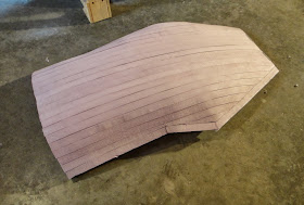
With the hood finally skinned with 1/4 thick foam strip the smooth shape is really coming together.  It took me four hours to do this work and I am happy with the results.  


 This is a good shot of the nose and hood from the front of the velomobile.  I will be more than happy to get the outer skin fiber glassed as just the simplest thing can put a dent in it.  Easy enough to repair but just one more thing to be careful of while working around the vehicle at this point.  You can just see the hinges for the hood just above the nose in this shot.  I still have to grind down some of the wooden mounts so that once the body is fiber glassed very little of the hinges will be seen.  A nice look to be sure.


Another good shot of the left side of the velomobile.  You can see some of the indentations in the foam on the side of the body.  Again this is an easy fix as the body still needs to be completely sanded into shape before fiber glassing can begin.  All the little voids that I can see in between the foam strips will be puttied with an epoxy resin/micro balloon mixture and then more sanding to get the body just right. 
  Before any of this work can begin I will have to fiber glass the underside of the newly skinned hood.  I have to cut the ribs where the hood seam will be next and then the glassing can begin.  Not a hard  task to cut the hood from the body but just something that I will have to be careful with so that I don't make more work for myself in the process.


I am currently still working on the final details that will complete the tail end of the vehicle and I should have everything pretty much ironed out in the next few days.  Once I get parts made I will post that portion of the assembly when I get that far along.


One other thing that I saw today that I want to change is the opening of the cockpit for the velomobile.  As I sat in it  I was able to take a good look at how much room I actually need.  In this photo you can see a foam strip that I laid down on top of the body.  I plan on closing up the cockpit opening to fill in the small triangular area that you see here.  This will make the cockpit look a bit more closed in.  But not make it so small that I will have a hard time sitting in the drivers seat.  Still will have lots of shoulder room. 
  Total hours on the project so far have now jumped up to 338.5 hours.  A lot of work but fun work. As long as it puts a smile on my face it is time well spent.