Tuesday, June 26, 2012

Another Good Day On The Gyrokite Project


The Gyrokite project continues today with these photos of the parts that I made on my Makerbot 3D printer of the landing skid assembly.  


This is one of the landing skids for the Gyrokite.  Both skids are exactly the same and I designed them to be symmetrical in shape so that I did not need to have a left and right skid for the project.  The skid is 1/4 inch square at the base and is 6 inches long by 7/8ths of an inch tall.


This is the skids by themselves as they would be set up for the assembly of the landing skids.


Here the cross members are added to the assembly with 10-32 bolts and nuts.  The nuts are inserted into receiving slots in the landing skids and the bolts then are inserted through mounting holes in the cross members to hold it all together.  


These last two photos show the addition of the internal mast framework for the rotor blades mounting shaft.  This part has internal slots again to mount the part to the rear cross member with more 10-32 hardware.  On the sides of the mast framework are additional mounting holes with fuselage.  Internal nuts are recessed into matching holes to hold the nuts in place when attaching the fuselage side to the internal framework.  This will make more sense once the final assembly has taken place and I can get photos of it all going together posted here. 
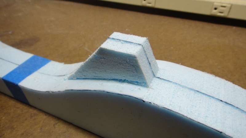
All of the parts for the landing skid assembly that I have shown you here are not filled solid with plastic from the Makerbot printer.  In actuality the parts are internally crisscrossed with a honeycomb of plastic to give each part strength yet make them lightweight. This will help a lot in keeping the weight down on the entire assembly when I want to fly it.  

  On another note about this project as it was quite windy here yesterday I did a little test of one of the main rotors from a suggestion made by my brother Dennis.  I took the rotor shaft and one of the rotor blades and just held them at arms length into the wind to see how well it would spin.  To put it simply....WOW!  I was just barely able to hold it away from my body as the blade being three feet long was whipping around on the shaft at quite a speed.  Even enough speed to make an actual helicopter sound as it spun up in revolutions. WHOOP, WHOOP, WHOOP!  I am more encouraged now that this project has a real chance of working out the way I have planned.  If all else fails that I do not get enough lift from the 36 inch rotors I can always make them longer and try again.  But for now I think these will work out just fine.  A good test to be sure and another good day at the Tinker's Workshop!

Monday, June 25, 2012

The Gyrokite Project Continues


In my last post I started work on an update of an old design of a gyrocopter kite that was made in the 1960's.  Today I will show you another couple of steps in the process of building the Gyrokite.  These being the tail section and the main rotors. 
  The tail section of the gyro is made out of fiberglass which looks complicated to make but when broken down to simple steps is very easy to build.


I started first with an inch and half block of blue styrofoam nine inches wide and six inches long.  This is the exact same stuff that you put into your house to insulate it from the cold and can be bought at your local home supply store...aka Lowes, Menards, etc.  The block is cut on both sides at a 45 degree angle and then the top edges are rounded off using sandpaper. 


Next four layers of 8 oz. fiberglass cloth and resin are applied to the surface of the block making sure that at least four inches of the block are covered with uniform smooth layers.  This will make the actual surface of the tail section.


After the fiberglass has cured over night the block is cut using a band saw.  The three inch wide middle section is what I was after and the rest of the material can be scrapped.


I then did some additional marking on the newly cut block to get the outline of the tail section that will be cut next again using the band saw.


Here the tail section is starting to take shape after the cutting.


Using a hand held "hotwire" tool I started removing the unneeded styrofoam from the fiberglass tail section.  For those you who do not know what a hotwire is check out this site for styrofoam cutting tools that I use in my shop from The Hotwire Foam Factory.


In this photo is the tail section just after I've completely removed all of the styrofoam.  


Now with the tail section completely sanded it is ready for priming and more sanding before the final paint is applied.  This tail section will be attached to the underside of the fuselage of the Gyrokite with mounting hardware.

Sunday, June 24, 2012

A Blimp, Some Rockets And A Gyrocopter!

The last six or seven weeks I have been doing work on my house which has not been a lot of fun.  Not  that I had major problems with the renovations that I had planned.  I just am not a big fan of painting, period.  Now that the three bedrooms are completely done I am more than happy to get back to projects that have been idle for a while and are way more fun to work on.  

 
The last post was about my new Makerbot Replicator 3D printer that I had just purchased for the workshop.  I printed off a couple of strange looking white block like parts.  Now you will see what these parts are for.


These mounting blocks are now part of a base for my Blimp project that I had built way back in November 2011.  The blimp was originally set up to be hung from a ceiling.  I did not want to do this at my house so I decided to make this simple mount for it instead.  The blimp easily slides into the mounting blocks and now can be put anywhere in the house that I wish to show it off.  I still want to paint the base parts but for now this will do to show you what the first parts from the Makerbot were made for.

  Along with these parts I was able to print some very small parts for my son Eric who is working on a project of his own.  Here is what I came up with for him.


Eric needed some very small rocket tokens for a board game he is creating.  With the new Makerbot Replicator I was able to print what you see here for his game.  All the parts were printed in white plastic to start and simply were painted various colors for each player.  I could have printed each rocket in different colors but being as he only needed so few it was just simpler to paint the parts instead. The quality of the prints as you can see turned out very well for being as small as they are.

  The next project that I have been working on is another rather large and complicated project that is as much of a challenge as it is a work of art.  I came across this old file online of a gyrocopter kite that was made in the 1960's.  This is my version of that project.
This gyrocopter was originally designed in 1962 by Roy Clough.  Here is the link to the free download of these plans.


I liked the idea but wanted to make a gyrocopter kite that was more modern looking with a fuselage that had a 3D shape to it instead of just a flat surface you see here.   


My Gyrokite is a bit more high tech than the original design as it is made with wood, fiberglass, and 3D printed parts.  I just will have to keep my fingers crossed that it will fly as well as it looks.  Here is my design and what I have done so far.


  The first attempt at building the fuselage started with this center spine that I cut on my CNC machine.  


I then cut styrofoam ribs that slid on to the spine.  It looks good and that was about as far as it goes with this idea.  It soon became apparent that the spine was more weight than I wanted and it would be difficult at best to cover the ribs with fiberglass. So this idea was discarded.


I next took the fuselage spine and used it as a template to cut a solid foam fuselage.


Careful cutting of the foam mast housing was done next with an Exacto blade and a steady hand. 


The edges of the fuselage is now hand sanded to make a nice smooth shape using sand paper.


Both sides of the fuselage is taped together and sanded smooth again.  This time attention was paid to the goal of getting both sides of the fuselage to be mirror images of one another.  I think my efforts here worked out very well.


Here the foam is fiberglassed with several layers of resin and cloth.


 Looks kind of fuzzy at this point but at least now it has a nice hard surface to make the fuselage with. The edges will be trimmed for the next step so that the edges are smooth and cleaned up.


Rough putty made from fiberglass resin and a micro balloon mixture is applied.  Kind of looks like frosting.


Fuselage parts are now ready for primer after the first session of sanding had been done.  Already starting to look a lot better.


Wet paint primer is applied.

More sanding and ready for more primer.

Now the fuselage sides are primed, sanded, primed, sanded, primed sanded...etc.  To make it short primer and a lot of wet sanding until the parts look this good.  The painting of the fuselage will not be done until all the internal mounting parts have been installed and all holes have been drilled.  I plan on painting the fuselage red with a black gloss windshield that will be painted on. So this is a very good start for the gyrokite project.   
  Coming up in the next posts will be photos and text about the making of the main rotor blades, tail section, landing skids, and internal Makerbot mounting parts that hold everything together.  Lots of great info on this project so check back soon and you'll see how this project is progressing.  

Sunday, June 17, 2012

Christmas Comes Early To The Tinker's Workshop!

Weeks and weeks ago (six to be exact) I placed an order for a new Makerbot Replicator 3D printer for the workshop.  At that time I was informed that my order would take anywhere from 10 to 12 weeks for the new tool to arrive. I was pleasantly surprised a couple of days ago to have UPS show up at my door with my new favorite tool / toy!  If you have been following along with my blog for a while you will know that I have been traveling 70 miles one way to get to use  another Makerbot 3D printer at the QC Co-Lab  maker space in Davenport Iowa. It has finally come time for me to buy my own.  So here are photos of my new acquisition.

 The arrival of the new 3D printer could not have come at a better time as I have been more than busy doing renovations on my bedrooms in my house and building a new platform bed to put into my room. (See earlier posts of this project)  I was more than happy to take a break from all of the remodeling, painting, staining, varnishing and dust and dirt to get to play with this impressive machine.  Now progress can be made on projects long shelved because of the lack of this tool.


The new Makerbot Replicator 3D printer is the latest and greatest offering from the Makerbot company.  After only working with this new printer for about five hours I am already VERY impressed with it's capabilities. I unpacked it from the shipping box the first night and inside of an hour I was making perfect parts.  This has got to be the Apple Ipod of 3D printers.  Very easy to set up and use right out of the box. The main structure of the printer is roughly 18" wide, 15" tall and 12 1/2 deep.  The printer has a build area of 6 x 9 x 6 inches.  This for me was a big selling point for most of the projects I have worked on and have planned. The fact that I did not have to be an electronics genius to put it together was an even bigger plus.  From out of the box to up and running in less than an hour works for me.


 On the front of the Makerbot Replicator is an LCD screen and control buttons that walk you through everything from setting up the machine to actually using it on a simple easy to read display.  I am talking English here not techno babble that is Greek or should I say Geek to the rest of us in the normal world. 


After setting up the build platform so that it was perfectly level with the dual print heads in the Replicator I printed this little test cube to see how things looked.  All looked well at this point so I thought I might as well try and print something for a small project that I currently have planned and is much more useful.


These two pieces were the first real parts from the Makerbot Replicator that will be used in an upcoming project.  On a scale of 1 to 10 I would have to say that these parts were very close if not a ten in my book of parts that I have made with a 3D printer.  The filament that is used in the new printer is 1.75 mm in diameter which gives a very fine extrusion for a smoother finish that looks terrific. The Makerbot Replicator has dual print heads and is fed by two separate filament spools mounted on the back of the printer.
   Both of these parts took 2 hours 10 minutes each to print. I never once touched the machine during the printing of them.  Press a button and let it do it's thing.  Amazing to create something like this and not have to babysit the machine to get what you want. But it's not hard to sit and watch parts being made.  Very entertaining and productive at the same time. These parts are 1.5 inches thick, 2 inches wide and 2.5 inches tall.  The inside of the shapes are a honey comb matrix structure that is strong and very light weight.  With this matrix the shapes use very little plastic.  Pennies on the dollar to make prototype parts such as these. Let the designing and building of new projects begin!

Saturday, June 9, 2012

The Platform Bed Project Is Completed!

After a very long day, and half of the night yesterday I completed work on the platform assembly for the platform bed project.  Here is the sequence of work that needed to be done.


This photo is the platform assembly separate from the base assembly where it will be mounted.  It is made up of 2x4's and wrapped on three sides with oak 1x6's.  This assembly is screwed together and is light enough for two people to move if the bed should need to be moved in the future.


These two photos show the platform mounted to the platform base.  The platform is flush at the top of the platform base and the three remaining sides overhangs each side by 6 and 1/2 inches.  


In order to keep the platform in position on the platform base four "L" brackets were screwed into the platform and base.  It would not be good to have the platform move when you tried to get into or out of the bed.  Would make for a bad start or end to your day.


Half inch plywood was mounted next to the inside of the platform using wood screws.  This plywood was placed over the entire inner surface of the platform. Also in this photo the headboard riser was put into position.  This rests on the plywood and straddles the platform frame on both sides.  It slid into place without a hitch. (Great when a plan works out.)


In this shot the new mattress and waterbed headboard were placed on the bed.  The headboard is heavy enough to just sit on the headboard riser so no screws are needed to keep it in place.  This is good but could not be done by one person as it is that heavy.  The staining I had done on the headboard riser and the platform lip parts matched perfectly with the headboard too!


Now the bed is done with completely new linen ready to be jumped into tonight!  The lighting all works again should I want to do some reading before I call it quits for the day with an exhausted body and a smile on my face.  Needless to say I will be more than happy to take at least the next couple of days off and just relax and enjoy the completion of this project.  Gives me time to recuperate and dream up my next project.  Hope you enjoyed these last few post as much as I did creating this project.